Periphery level, The operating modes of the bus coupler, Power on selftest bus terminal test structure list – BECKHOFF BC3100 User Manual
Page 9: Bus terminals bus coupler field bus 24 v dc
Basic information
BC3100
9
Setting up the power levels
in the bus terminal system
Periphery level
Bus terminals
Bus coupler
Field bus
24 V DC
K-bus
The operating modes of the bus coupler
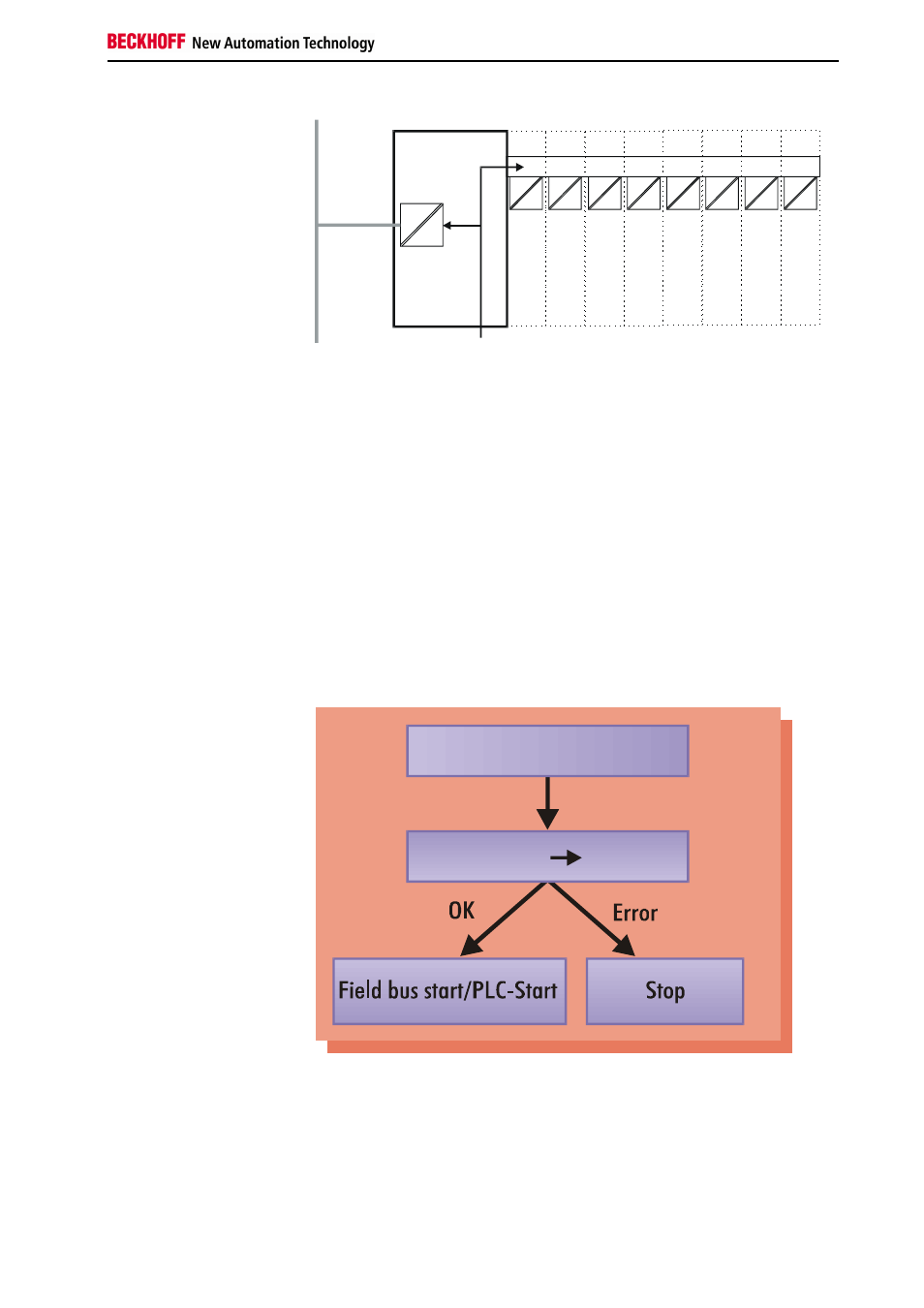
After power on, in a "self-test" the bus terminal controller checks all
functions of its components and communication by the K-bus. The red I/O
LED flashes during this phase. After successful completion of the self-test,
the bus terminal controller begins to test the plugged in bus terminals (bus
terminal test) and reads the configuration. An internal structure list is
created on the basis of the bus terminals' configuration. The bus terminal
controller assumes the "STOP" operating state in the event of an error.
After error-free start up, the bus terminal controller assumes the "field bus
start/PLC start" state. If a PLC program is stored in the flash memory, it is
loaded and started regardless of whether the field bus is running. The
inputs of the PLC task have been set to zero during start up.
Start-up behavior of the bus
terminal controller
Power on selftest
Bus terminal test Structure list
Depending on the field bus functionality, the bus terminal controller reports
a possible error via the field bus. The BC3100 generally has to be restarted
after the error has been remedied.