4 pressure sensor, 3 valve principles, 1 solenoid valve – Bronkhorst IN-FLOW User Manual
Page 13: 2 vary-p valve
BRONKHORST HIGH-TECH B.V.
9.17.022
page 13
2) The CTA based LIQUI-FLOW model for flow rates up to approximately 1000 g/h.
The CTA based LIQUI-FLOW model basically consists of a small capillary tube with two sensing elements
placed around it. The upstream sensing element is a temperature sensor that is used to measure the
temperature of the liquid flowing through the tube. The downstream sensing element is a heater, which is
heated up to a certain temperature ∆T over the medium temperature. A patent application on the flow sensor
design has been submitted.
The heater power necessary to keep ∆T at a constant level is dependent on the mass flow. In the case of no
flow, a constant and negligibly small heating power is necessary. When a certain mass flow occurs, the
heater is cooled down. Therefore, the heating power has to be increased to maintain the adjusted
temperature difference. Thus, a different and unique heater power is produced for each value of the flow. The
measurement principle described is called Constant Temperature Anemometry (CTA).
The heater and temperature sensing element are electrically connected via a Wheatstone bridge
configuration that performs two features: first, it provides the heater with the necessary heater power and
second, it takes care of the temperature compensation. Finally, a signal conditioning circuit provides a linear
output signal. The transfer function between the liquid mass flow and the linear output signal can roughly be
described with the equation:
V
signal
= output signal
K
= calibration constant
m
p
signal
c
K
V
Φ
⋅
⋅
⋅
≅
2
l
c
p
= specific heat
l
= heat conduction coefficient
Φ
m
= mass flow
1.2.4 Pressure sensor
The EL-PRESS pressure sensor is formed by a piezoresistive bridge on the surface of a silicon crystal.
The sensor is mounted in a stainless steel construction and separated from the fluid by a thin metal
membrane. The chamber around the sensor is filled with oil to couple the pressure from the fluid to the
sensor.
1.3
Valve principles
Control valves are not designed to provide positive shut-off, although some models have excellent
capabilities for this purpose.
It is recommended to install a separate shut-off valve in the line if so required. Also pressure surges, as may
occur during system pressurisation must be avoided. The following models can be distinguished:
1.3.1 Solenoid valve
This is considered to be the standard (direct operated) control valve. In
general it is a normally closed solenoid valve. The plunger is lifted by the
force of the magnetic field of the coil. The orifice under the plunger is
removable for optimising the orifice diameter. Also a normally opened
solenoid valve is available.
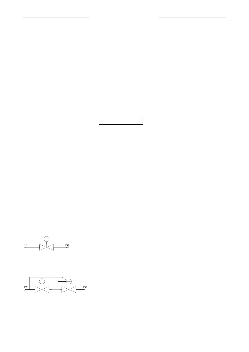
1.3.2 Vary-P valve
For process conditions where up- and downstream pressure vary
much, a special type of valve, VARY-P has been designed. This
valve consists of two valves, a solenoid operated control valve
and a fixed adjusted pressure compensation valve.
flowcontrol
valve
pressure
compensating
valve
flowcontrol
valve