8 analog operation, 9 bus / digital operation – Bronkhorst IN-FLOW User Manual
Page 27
BRONKHORST HIGH-TECH B.V.
9.17.022
page 27
0V common
-
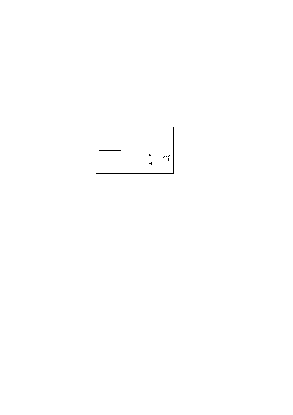
Current output signals
Sourcing
instrument
output
I
+
mA
3.8
Analog operation
Digital instruments can be operated with analog signals through the 9-pin sub-D connector or 8DIN
connector. The instruments are compatible in use with
analog instruments on this point.
Analog operated instruments can be hooked-up using an 8-wire shielded cable with 9-pin D-connectors or
8DIN connectors, connected according to the Bronkhorst High-Tech standard.
Each electronic p.c.board is set for one of the following output (and corresponding input) signals:
Signal
output (sensor)
input (setpoint)
code
signal
signal
A
0…5 Vdc
0…5 Vdc
B
0…10 Vdc
0…10 Vdc
F
0…20 mA (sourcing)
0…20 mA (sinking)
G
4…20 mA (sourcing)
4…20 mA (sinking)
For meters only the output signal is available.
At analog operation following parameters are available:
- measured value
- setpoint (controllers only)
- valve voltage (controllers only)
Note:
When operating the instrument through the analog interface it is possible to connect the instrument to any
supported fieldbus system (or RS232-interface with special cable) for reading/changing parameters (e.g.
controller response or other fluid selection).
For FLOW-BUS versions of the instruments a readout/control module for digital instruments can be
temporarily connected to the RJ45 modular jack plug.
3.9
BUS / digital operation
Operation via fieldbus reduces the amount of cables to build a system of several instruments and offers more
parameter values to be monitored/changed by the user.
See instruction manual: operating digital mass flow / pressure instruments for more details (document nr.
9.17.023).
Operation by means of a fieldbus adds a lot of extra features (compared to analog operation) to the
instruments.
Such as:
- setpoint slope (ramp function on setpoint for smooth control)
- 8 selectable fluids (calibration settings for high accuracy)
- direct reading at readout/control module or host computer
- testing and self diagnosis
- response alarm (|setpoint-measure| too high for too long time)
- several control/setpoint modes (e.g. purge/close valve)
- master/slave modes for ratio control (FLOW-BUS only)
- identification (serialnumber, modelnumber, device type, user tag)
- adjustable minimal and maximal alarm limits
- (batch) counter
- adjustable response time for controller when opening from zero
- adjustable response time for normal control
- adjustable response time for stable control (|setpoint-measure| < 2%)