11 s, 12 f, 13 f – Bronkhorst Multibus User Manual
Page 19
BRONKHORST
®
Page 19
Operational instructions for digital multibus instruments
9.17.023
4.10.1 Dual interface operation
When operating a controller (reading measured value and sending setpoint) for proper operation it is important that
the controller gets its setpoint from the right source. Setpoints may come from different sources: analog input, field
bus interface, RS232 interface or may be overruled by close valve or open valve (purge) commands. Therefore it is
important to know what the setpoint source of the controller is. This can be set by means of parameter control mode
(DDE parameter 12).
In some cases it is possible that the setpoint may come from 2 sources at the same time. The last setpoint send will be
valid and send to the controller. This is the case in control mode = 0, when setpoints may come through any field bus
interface or RS232. However, there could be situations where control over the instrument seems impossible. This is
the case when the instrument comes into a safe-state e.g. when field bus communication is disturbed or disconnected.
The valve will be forced to a safe state automatically: closed (NC) or fully open (NO).
In case you want to get control back via RS232 operation, you have to change the control mode. When control mode
gets value 18, safe state will be overruled and sending setpoints via RS232 interface will have effect on the controller
again. ‘Control Mode’ value 18 will be lost after power off and power on of the instrument.
4.10.2 Tuning, test and calibration mode
These are special modes to prepare the instrument for either a tuning, test or calibration action. These modes are used
by Bronkhorst service personnel only and are not meant for customer use.
4.11 S
LAVE
F
ACTOR
float
0…500
RW
N
139
33/1
Depending on the Setpoint/control mode a slave factor can be set.
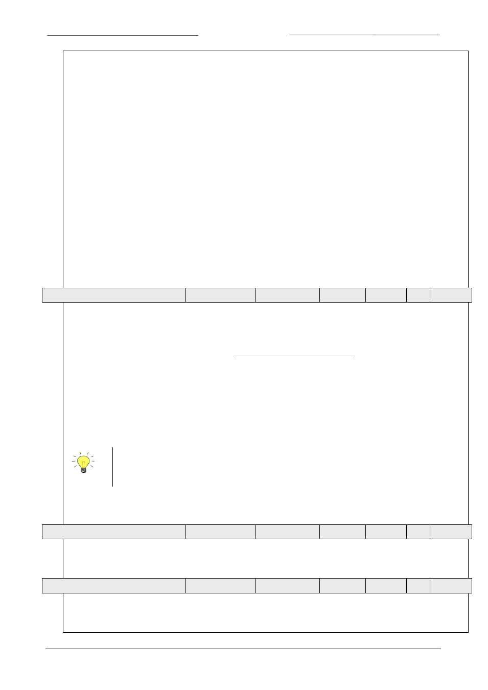
In master/slave or ratio control the setpoint of an instrument is related to the output signal of another instrument.
100%
factor
slave
al
Outputsign
setpoint
(master)
(slave)
•
=
Digital instruments offer possibilities for master/slave control via the FLOW-BUS. The output value of any instrument
connected to the FLOW-BUS is automatically available to all other instruments (without extra wiring). When
master/slave control is wanted the instrument can be put in control mode 2 or 13, depending on how the slave factor
should be set (see table above). Through FLOW-BUS an instrument can be told that it should be a slave, who should be
its master (DDEpar. 158 ‘Master Node’) and what should be the slave factor to follow the master with. It is possible to
have more masters and more slaves in one system. A slave can also be a master itself for other instruments.
These options are available for FLOW-BUS or RS232 instruments only.
Output signals from master can be received via FLOW-BUS only.
Slave factors can also be changed via RS232.
Master/slave is meant here for controlling purposes and has nothing to do with master and slave behavior on field bus
networks.
4.12 F
LUID NUMBER
unsigned char
0…7
RW
N
24
1/16
Fluid number is a pointer to the set of calibration parameters. Each selectable fluid has its own set of calibration
parameter values. Fluid number is an unsigned char parameter (DDEpar. 24 ‘Fluid number’) in the range of 0...7, where
0 = fluid1 and 7 = fluid8. Up to 8 fluids can be stored in one instrument. Default value = 0 (fluid 1).
4.13 F
LUID NAME
unsigned char[10]
a…z / 0…9
RW
Y
25
1/17
Fluid name consists of the name of the fluid of the actual selected fluid number. Up to 10 characters are available for
storage of this name. This parameter is secured and read-only for normal users (it is written during calibration at the
factory). Default value is “Air”.