Bronkhorst Multibus User Manual
Page 27
BRONKHORST
®
Page 27
Operational instructions for digital multibus instruments
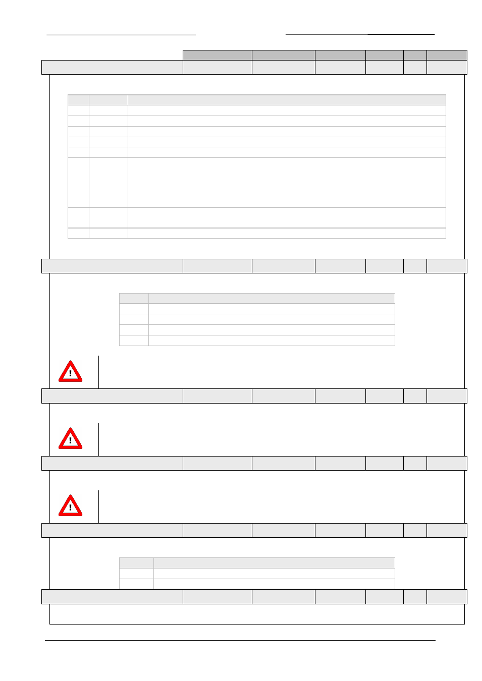
9.17.023
Data Type
Range
read/write
Secured DDE Proc/par
6.3 A
LARM INFO
unsigned char
0…255
R
N
28
1/20
This parameter contains 8 bits with status information about some (alarm) events in the instrument.
Bit
low (0)
High (1)
0
no error An error occurred:
Alarm register 2 contains an error
1
no error A warning occurred:
Alarm register 1 contains a warning
2
no error Minimum alarm:
Sensor signal < minimum limit
3
no error Maximum alarm:
Sensor signal > maximum limit
4
no error Batch counter:
Reached its limit
5
no error This bit only:
Power-up alarm (probably power dip occurred)
Together wit bit 2 or bit 3:
Response alarm message
(setpoint-measure too much difference)
(bit 2 or bit 3 indicate if difference is positive or negative)
6
no error Master/slave alarm:
master output signal not received or slave factor out of
limits (> 100%)
7
no error Hardware alarm:
check hardware
6.4 A
LARM MODE
unsigned char
0…3
RW
N
118
97/3
Available alarm modes for device:
Bit
Description
0
Off
1
alarm on absolute limits
2
alarm on limits related to setpoint (response alarm)
3
alarm when instrument powers-up (e.g. after power-down)
Not all modes are available for all field busses. E.g. for DeviceNet only mode 0 and 1 are available.
6.5 A
LARM MAXIMUM LIMIT
unsigned int
0…32000
RW
N
116
97/1
Maximum limit for sensor signal to trigger alarm situation (after delay time).
Minimum limit ≤ Maximum limit ≤ 100%
6.6 A
LARM MINIMUM LIMIT
unsigned int
0…32000
RW
N
117
97/2
Minimum limit for sensor signal to trigger alarm situation (after delay time).
0% ≤ Minimum limit ≤ Maximum limit
6.7 A
LARM SETPOINT MODE
unsigned char
0…1
RW
N
120
97/5
Available alarm setpoint modes for device:
Value Description
0
no setpoint change at alarm
1
new/safe setpoint at alarm enabled (set at alarm new setpoint)
6.8 A
LARM NEW SETPOINT
unsigned int
0…32000
RW
N
121
97/6
New/safe setpoint during alarm situation until reset.