6 alarm / status parameters, Eneral, Unctional alarm schematic – Bronkhorst Multibus User Manual
Page 26
BRONKHORST
®
Page 26
Operational instructions for digital multibus instruments
9.17.023
6 ALARM / STATUS PARAMETERS
6.1 G
ENERAL
Bronkhorst digital instruments have a build in alarm function. It is used to indicate several types of alarms:
• System errors
• System warnings
• Min/max alarms
• Response alarms
• Batch alarm
• Master slave alarms
The alarm can be read out using parameter alarm info. After an alarm a setpoint change can be set. This means the
setpoint will go to the set value after an alarm occurs. A delay can be set to prevent reaction to glitches in
measurement or power. How an alarm can be reset is controlled by the parameter “reset alarm enable”. It can bit-
wise be set to automatic, reset, external or keyboard/micro-switch. After the reset the alarm stays present during the
alarm delay time. In the functional schematic below the basic alarm function is explained.
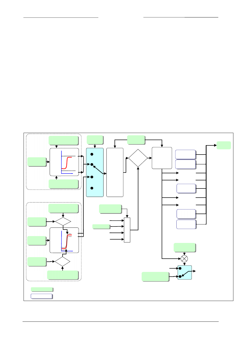
6.2 F
UNCTIONAL ALARM SCHEMATIC
Alarm
mode 0..3
Alarm delay
time 0..255
Alarm new
setpoint 0…32000
Alarm setpoint
mode 0,1
Reset alarm
enable 0..15
80%
15%
Minimum alarm
limit 4800 = 15%
Maximum alarm
limit 25600 = 80%
Measure
0…32000
+3%
-4%
Minimum alarm limit
= 1280 = 4%
Maximum alarm
limit = 960 = 3%
Measure
0…32000
Setpoint
0…32000
-
Off
Power-up
Max
Min
Min
Max
Hardware
alarm
Master/
Slave alarm
Batch
counter limit
Warning
message
Error
message
+
Old Setpoint
Setpoint
Automatic
External
Keyboard/
Micro-switch
After Reset
alarm will still
be present
during “Alarm
delay time“
Reset
alarm
&
Setpoint
0…32000
bit[0]
bit[1]
bit[4]
bit[6]
bit[7]
Reset
Response
alarm
Min/Max
alarm
Alarm
info 0..7
Min. Alarm
Max. Alarm
Power-up
Response
bit[2]
bit[3]
bit[5]
bit[5]
bit[0]
bit[1]
bit[2]
bit[3]
Min/max
Response
Alarm must
be present
during
“Alarm
delay time“
before
activation
External
Parameter