5 control parameters, 1 pid-k, 2 pid-t – Bronkhorst Multibus User Manual
Page 23: 3 pid-t, 05 * response old response new
BRONKHORST
®
Page 23
Operational instructions for digital multibus instruments
9.17.023
5 CONTROL PARAMETERS
The controlling algorithm for the valve handled by the micro-controller consists of several parameters which can be
set via the BUS/RS232. Although many parameters could be accessed via BUS/RS232, Bronkhorst advises not to
change these parameters because during manufacturing they have got optimal values for their purposes. Changing of
controller settings should be performed by or under supervision from trained service personnel only.
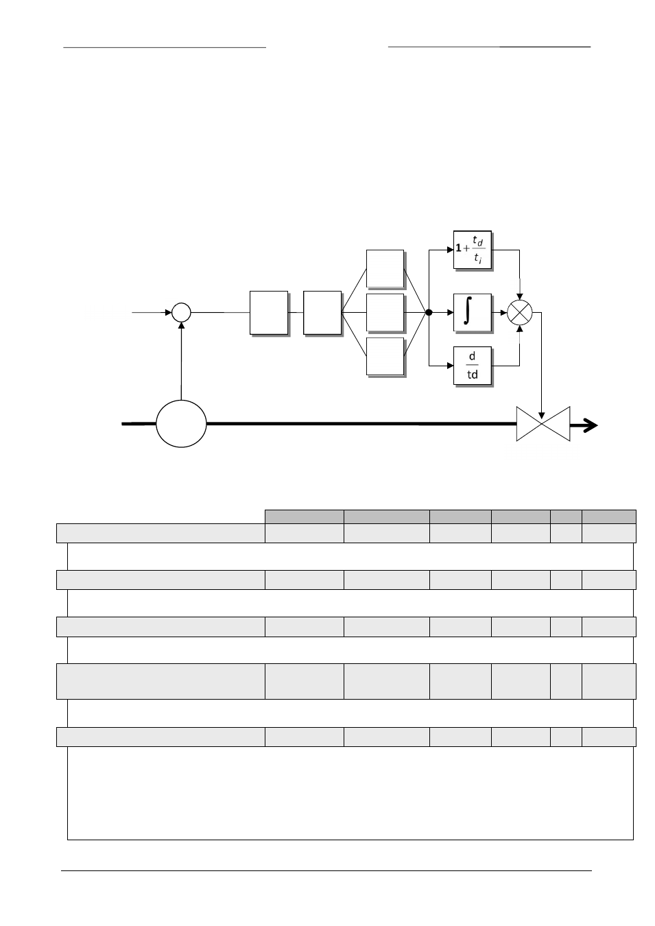
The picture below shows the basic controller diagram of the digital instrument. It consists of a standard PID controller
with a number of add-ons.
Basically, when a faster or slower controller response is needed, only the controller speed (Kspeed) or PID-Kp has to
be changed.
Data Type
Range
read/write
Secured
DDE Proc/par
5.1 PID-K
P
float
0…1E+10
RW
Y
167
114/21
PID controller response, proportional action, multiplication factor.
5.2 PID-T
I
float
0…1E+10
RW
Y
168
114/22
PID controller response, integration action in seconds.
5.3 PID-T
D
float
0…1E+10
RW
Y
169
114/23
PID controller response, differentiation action in seconds.
5.4 C
ONTROLLER SPEED
(Kspeed)
float
0…3.40282E+38
RW
Y
254
114/30
This parameter is the controller speed factor. PID-Kp is multiplied by this factor.
5.5 O
PEN FROM
Z
ERO RESPONSE
unsigned char
0…255
RW
Y
165
114/18
Controller response when starting-up from 0% (K
open
,
Kp multiplication factor when valve opens).
Value 128 is default and means: no correction.
Otherwise controller speed will be adjusted as follows:
Zero)
from
Open
(128
1.05
*
response
old
response
New
−
=
K
open
K
normal
K
stable
S
+
-
Sensor
Control Valve
Flow
Setpoint
K
p
P
I
D
K
speed
+
+
+