Cloud Electronics PM16 User Manual
Page 21
PM4/8/12/16 & PM4/8-SA Installation and User Guide v1.0
21
replacement before mounting the PM on the wall.
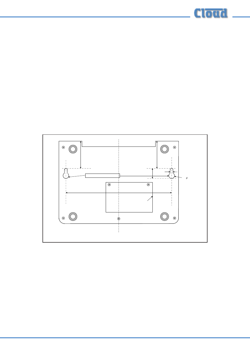
The metal baseplate of the PM is fitted with two keyhole slots which provide a simple
method of wall mounting.
The PM can be wall-mounted on two round-head or pan-head screws with heads of
between 5 and 10 mm dia. At the desired location, drill two holes in the wall 183 mm
apart horizontally. Use a drill appropriate for the wall construction and type of wall
fixing employed. Insert the screws and tighten until approx 4-5 mm of the screw
shafts are still visible. Slide the PM over the screw heads using the keyhole slots, so
that the rubber feet act as spacers between the PM baseplate and the wall. If the PM
is not tight against the wall, remove the PM, adjust the length of screw protruding and
try again. Repeat until a good tight fit is obtained. Refer to the illustration below for
drilling instructions.
Fitting the MI100166 gooseneck microphone
The standard gooseneck mic supplied with the PM Series is 300 mm in length, and
this may be inconveniently long if the PM unit is wall-mounted. A 140 mm version,
Part No. MI100166, may be ordered separately from Cloud Electronics, and fitted
instead.
To replace the gooseneck mic, remove the baseplate of the PM unit as detailed at
“Accessing the internal PCB” on page 20. It will be seen that the thin twin-and-
screen cable from the gooseneck itself terminates in a screw terminal connector on
the right-hand side of the PCB (see “PCB layout diagrams” on page 49 for location