Mixer – Cloud Electronics PM16 User Manual
Page 45
PM4/8/12/16 & PM4/8-SA Installation and User Guide v1.0
45
IN
OUT
OUT
CAT-5
CAT-5
CAT-5
CAT-5
CAT-5
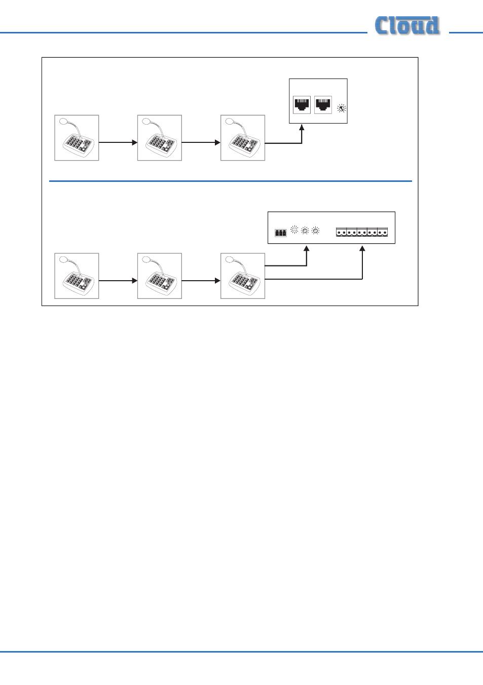
(with Digital Paging Interface)
IN
OUT
IN
OUT
AUDIO OUT
ZONE ACCESS CONTROL
Mixer
IN
OUT
MIC INPUT
PAGING ACCESS
Mixer
+12V
Z1 Z2 Z3 Z4 Z5 Z6 Z7 Z8
0V
LF
HF
GAIN (dB)
50
1
2
3
10
+
-
-
+
(with Analogue Paging Interface)
CDPM
GAIN (dB)
IN
THRU
-10
+10
Note that there is no restriction as to the PM model which is the ‘last’ in the chain
– i.e., that which connects directly to the mixer. All PM models support all 16 zones,
so in an extreme example, several PM16s could be daisy-chained with a PM4 as the
‘last’ microphone in the chain. All microphones on the system will have full access to
whichever zones are required.
See also “Cables and Connections” on page 27.
*The Digital Paging Interface also permits PMs to be intermixed with the older Cloud CDPM paging
microphones on the same network. Refer to the separate CDPM Installation manual for information
(available as a download from the Cloud website).
Maximum System Capability
Up to 32 PM microphones may be interconnected via the Digital Paging Interface.
Different models of PMs, including PM-SAs, may be mixed freely, and each may have a
zone offset applied, as required. The total CAT-5 cable run should be less than 1 km.
Power supply considerations
In a multiple-PM system, only the ‘last’ microphone in the chain – that which connects
directly to the host mixer – may be powered from the host, either via the Digital
Paging Interface (if available) or the analogue interface. Alternatively, it may be
powered via an external PSU such as the Cloud CPM-PSU. See “Using an External
PSU” on page 22 for full details.