Cloud Electronics PM16 User Manual
Page 28
PM4/8/12/16 & PM4/8-SA Installation and User Guide v1.0
28
IMPORTANT: The Digital Paging Interface is a data network, and thus must be
terminated at both ends. In a system comprising a single PM, this means terminations
must be set in both the PM and the host mixer. In systems with multiple PMs, it
means terminations must be set in the PM at the ‘end’ of the chain and the host
mixer. See “Terminating the Digital Paging Interface” on page 42 for details of how
to set terminations.
NOTE: If the Digital Paging Interface is used as the method of connecting the PM to
the host mixer, the two access glands at the rear of the unit for the audio output and
analogue control cables (see “Rear Panel” on page 11) will not be required.
Connecting the PM to a mixer via the analogue interface
In addition to the Digital Paging Interface, the PM incorporates an analogue interface,
permitting the PM to be used with any Cloud (or other) mixer which has an industry-
standard, short-to-ground access port for zone selection.
The connections for the analogue interface are on the internal PCB. Follow the
instructions on “Accessing the internal PCB” on page 20 on how to access this.
Two cables are required. The two cables are as follows:
1. Audio Cable:
The audio cable should be a standard two-core, screened microphone cable. This cable
should be fed through the rear cable gland labelled AUDIO OUT, and connected to
the screw-terminal block marked TERM8 on the internal PCB. Refer to “PCB layout
diagrams” on page 49 for location.
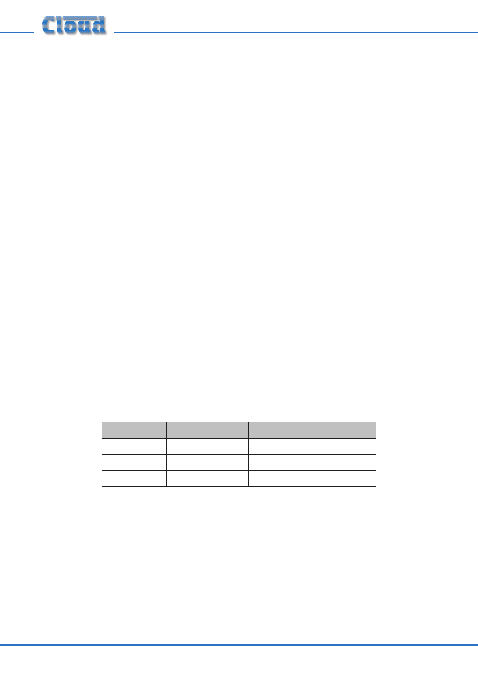
Connect to TERM8 as follows:
Terminal
Use
Typical Cable Colour
Hot
Phase (+)
Red
Cold
Anti-phase (-)
Black
Gnd
Screen
Screen