Cloud Electronics PM16 User Manual
Page 43
PM4/8/12/16 & PM4/8-SA Installation and User Guide v1.0
43
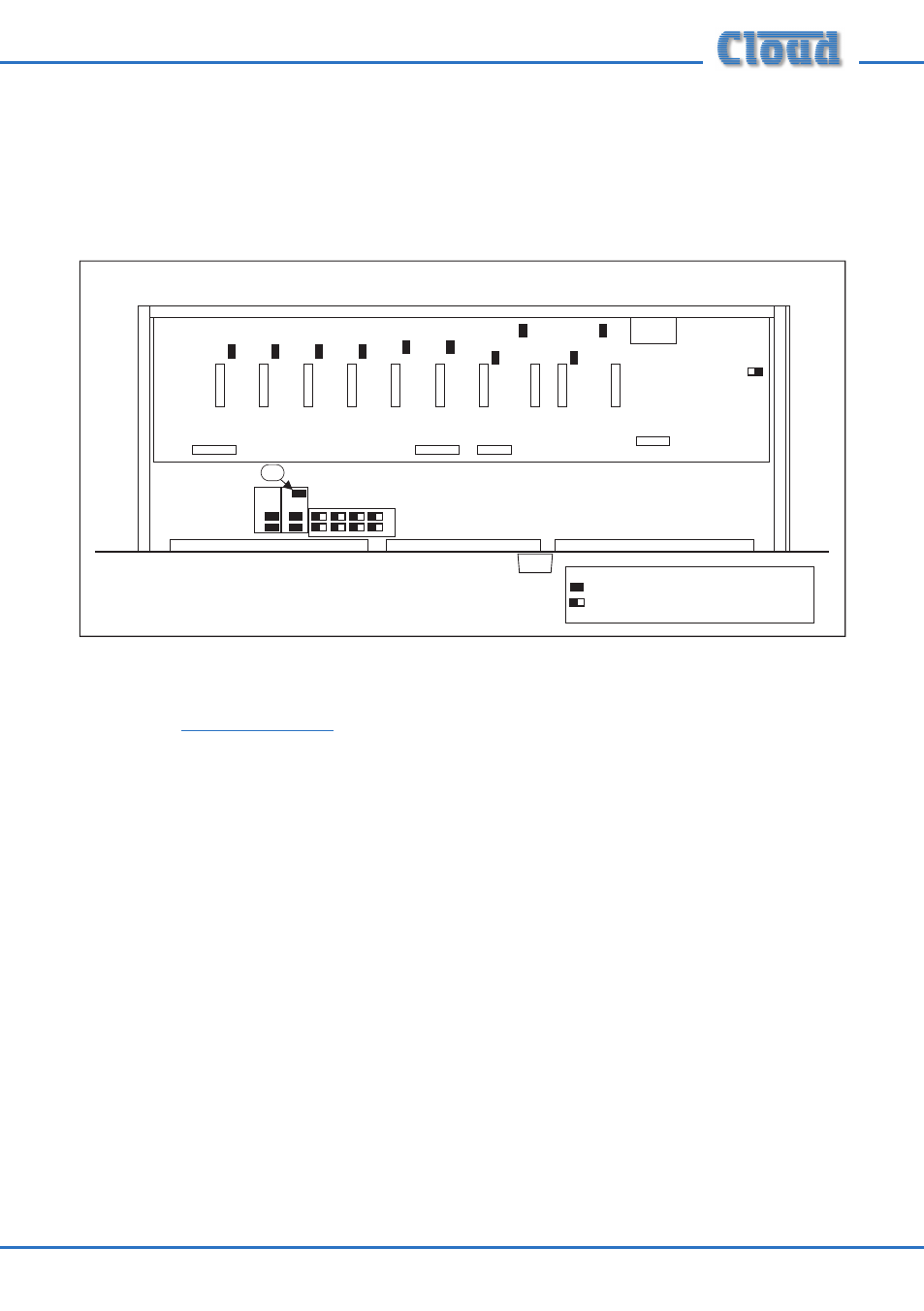
Setting the terminations on the Cloud DCM-1
The Digital Paging Interface is referred to in the DCM-1 documentation as the
‘CDPM bus’. The termination is set by the DCM-1’s internal jumper J2, and is ON
when J2 is in place. This is the factory default setting, and is unlikely to require
changing. The diagram below shows the jumper’s location.
J2
(UPPER PCB)
(LOWER PCB)
KEY:
Jumper with two possible positions; black
square indicates factory default setting.
Jumper with one position (i.e., present or not)
DCM-1 Jumper Locations
For details of how to set the host mixer’s Digital Paging Interface termination
correctly in other models, please refer to the documentation supplied with the mixer,
or refer to
www.cloud.co.uk
.
Confi guring dual purpose microphone inputs on the Host Mixer
NOTE: This section is only applicable to systems using Cloud Integrated Mixers
Models 36/50 or 46/50, or Zone Mixers Models CX263 or CX163.
On the above mixers, Mic 1 input needs to be confi gured for paging use with a Cloud
PM by enabling the Mic Access input on the rear panel. Without the Mic Access
input enabled, Mic 1 input acts only as a general purpose microphone input and is
permanently active.