Cloud Electronics PM16 User Manual
Page 29
PM4/8/12/16 & PM4/8-SA Installation and User Guide v1.0
29
2. Zone Selection Control Cable:
The zone selection control cable should be a multicore stranded type with an overall
screen. The number of cores required depends on the number of zones supported by
the particular PM model (PM4, PM8, etc.), and whether DC power is to be derived
from the host mixer via the control cable (see “Power Requirements” on page
22). One core is required for each zone to be connected, plus a core for the 0 V
connection, plus one further core for DC power, if needed.
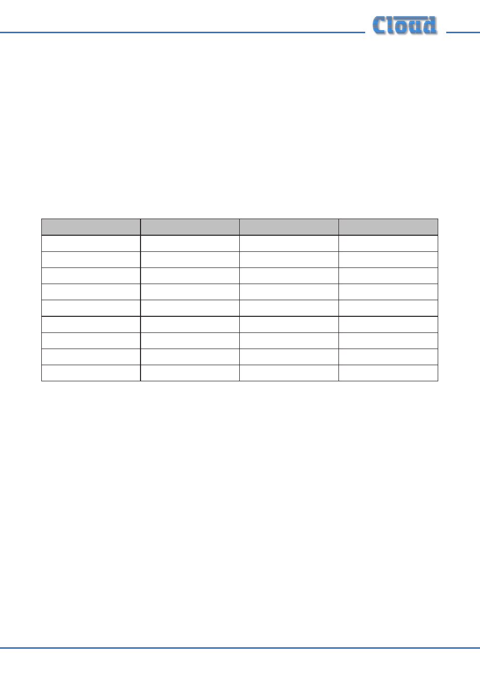
The control cable should be fed through the rear cable gland marked ANALOGUE
PORT, and connected to TERM1, TERM2 and TERM4 as detailed below:
Function
Connect To:
Function
Connect To:
Zone 1 Select
TERM2: Z1
Zone 10 Select
TERM4: Z10
Zone 2 Select
TERM2: Z2
Zone 11 Select
TERM4: Z11
Zone 3 Select
TERM2: Z3
Zone 12 Select
TERM4: Z12
Zone 4 Select
TERM2: Z4
Zone 13 Select
TERM4: Z13
Zone 5 Select
TERM2: Z5
Zone 14 Select
TERM4: Z14
Zone 6 Select
TERM2: Z6
Zone 15 Select
TERM4: Z15
Zone 7 Select
TERM2: Z7
Zone 16 Select
TERM4: Z16
Zone 8 Select
TERM2: Z8
0 V
TERM1: 0 V
Zone 9 Select
TERM4: Z9
+ V
TERM1: + V
Cable core colours will depend on cable type.
Refer to “PCB layout diagrams” on page 49 for locations of TERM1, TERM2 and
TERM4.
The cable screen should be connected to 0 V at the mixer end only. The analogue
control cable should have a total length of less than 100 m.
When all the connections have been correctly made, and, in the case of an SA model,
if an external message triggering cable is not required, tighten the locking clamps on
the two cable glands to ensure that no strain is placed on the terminals if the external
cables are tugged or stretched.