Cables and connections – Cloud Electronics PM16 User Manual
Page 27
PM4/8/12/16 & PM4/8-SA Installation and User Guide v1.0
27
Cables and Connections
Connecting the PM to a mixer via the digital interface
The rear of the PM is fitted with two RJ45 sockets labelled CAN PORTS. These
constitute the Cloud Digital Paging Interface, which connect the PM to the host
mixer, and/or to other PMs on a network in a multiple-PM system. Where a mixer has
facility for both digital and access contact connection, the digital connection should
be used.
The digital interface carries audio from the mic and (on SA models only) the message
stores, commands for zone selection and DC power on a single RJ45 connector. The
audio signal is directional, and is transmitted from the OUT connector to the IN
connector on the next microphone (or mixer) in the chain.
To connect the PM to a Cloud host mixer via the Digital Paging Interface, connect
the OUT port of the PM to the IN port of the mixer using CAT-5 cable and RJ45
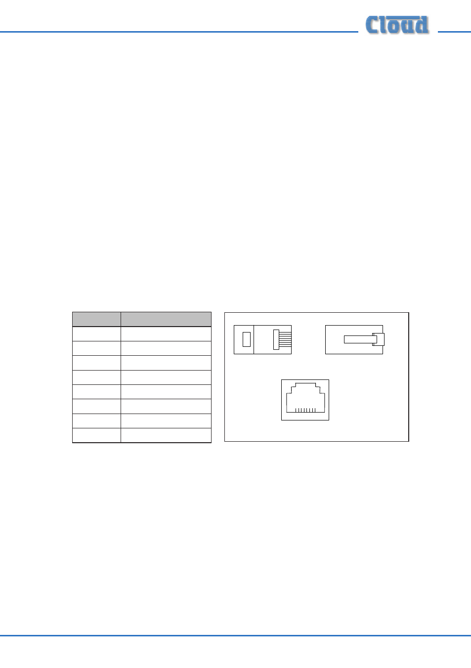
connectors. The cables should be wired pin-to-pin. The standard CAT-5/RJ45 wiring
convention is shown below:
PIN
CAT-5 CORE
1
White + Orange
2
Orange
3
White + Green
4
Blue
5
White + Blue
6
Green
7
White + Brown
8
Brown
The IN port will only be used when the system has more than one PM. To
interconnect two PMs, connect the OUT port of one to the IN port of the next ‘in
the chain’ using the same wiring standard as shown in the table above. See “Systems
with multiple paging microphones” on page 44 for full details.
A system using the Digital Paging Interface should have a total cable length of less
than 1 km.