Connecting a pm-sa for external message triggering – Cloud Electronics PM16 User Manual
Page 31
PM4/8/12/16 & PM4/8-SA Installation and User Guide v1.0
31
Connecting a PM-SA for external message triggering:
These connections are optional, and will only be required if the PM-SA’s internal
messages are to be triggered by external contact closure. Examples of such applications
include:
•
Programmed triggering via relays in external control systems (e.g., Crestron,
AMX, etc.)
•
Timed triggering by third-party timing equipment to broadcast messages at
regular intervals
•
Interface to BMS or fire control panels
•
Automatic triggering by PIR sensors for security purposes
•
Use of PIR sensors to provide promotional or other information
•
Connection to door access systems to provide visitor information
Providing connections for external triggering of the messages does not prevent
messages from being commanded by the PM’s own front panel buttons; these
continue to operate as normal.
The message trigger control cable may be a screened or unscreened multicore
cable with a number of cores suitable for the number of messages to be externally
triggered. UTP or STP data cable (i.e., CAT-5) is suitable. One core should be used as
a 0 V common connection for all the trigger inputs, or an overall screen may be used.
The control cable should be fed through the rear cable gland marked ANALOGUE
PORT (which it will have to share with an external zone select cable if an analogue
mixer interface is in use), and connected to the 9-way PCB screw terminal block
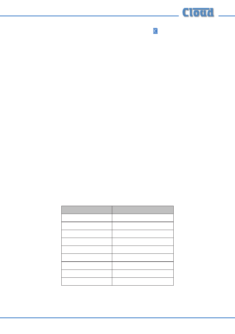
marked TERM10/TERM11/TERM12, as detailed below:
Function
Connect To:
0 V
TERM10/11/12: 0V
Trigger Group A
TERM10/11/12: M1
Trigger Group B
TERM10/11/12: M2
Trigger Group C
TERM10/11/12: M3
Trigger Group D
TERM10/11/12: M4
Trigger Group E
TERM10/11/12: M5
Trigger Group F
TERM10/11/12: M6
Trigger Group G
TERM10/11/12: M7
Trigger Group H
TERM10/11/12: M8