Functional description, 2 functional description, Figure 1-3. m&c block diagram – Comtech EF Data SNM-1001L User Manual
Page 36
Advertising
SNM-1001L Satellite Modem
Revision 1
Introduction
MN/SNM1001L.IOM
1–12
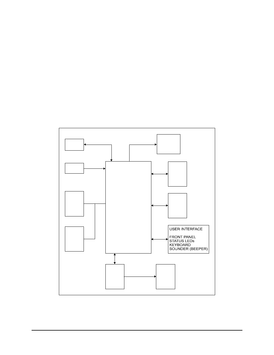
1.8.2 Functional
Description
The M&C card is composed of the following subsections:
• Microcontroller with Universal Asynchronous Receiver/Transmitter (UART)
• Digital-to-Analog Converter (DAC)
• Read Only Memory (ROM)
• Analog-to-Digital Converter (ADC)
• Read Access Memory (RAM)
• User Interface
• Fault and Alarm Relay
MODEM
11 MHz
CLOCK
I C BUS
2
RAM AND
REAL
TIME
CLOCK
ROM
(M&C,
BULK,
BOOT)
FAULT
AND ALARM
RELAYS
MICRO-
CONTROLLER
DAC
ADC
EIA-232
OR
EIA-485
9-PIN
REMOTE
Figure 1-3. M&C Block Diagram
Advertising