Channel monitor, Chassis ground, 1 channel monitor – Comtech EF Data EQ90 Series User Manual
Page 23: 4 chassis ground
EQ90 Series Group Delay/Amplitude Equalizer
Installation
Rev. 2
2–5
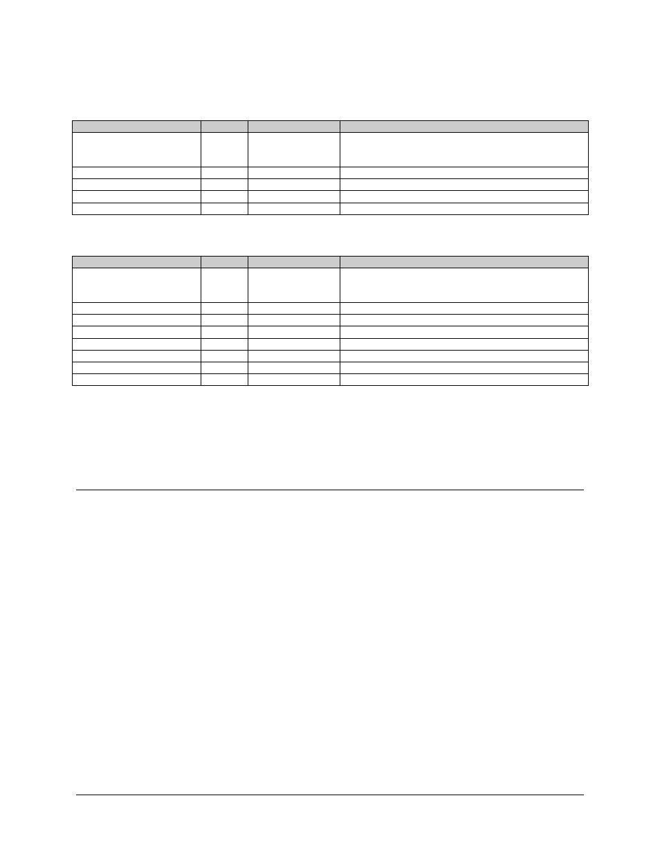
Table 2-1
. Single Channel
Equalizer Rear Panel Mating Connectors
Nomenclature and Item No.
Ref Des
Connector Type
Mating Connector
Primary Power Input
(11, Figure 2-2)
IEC-320 Socket with Belden 17250-C North American
18 AWG and NEMA UL Listed plug, or Belden Type 17820
with Harmonized Cordage.
IF Input (8)
A IN
Type BNC, female
IF Output (7)
A OUT
Type BNC, female
Channel A Monitor (13)
9-pin D, female
Ground (12)
E1
Table 2-2. Dual Channel Equalizer Rear Mating Connectors
Nomenclature and Item No.
Ref Des
Connector Type
Mating Connector
Primary Power Input
(1, 11, Figure 2-2)
AC1
AC2
IEC-320 Socket with Belden 17250-C North American
18 AWG and NEMA UL Listed plug, or Belden Type 17820
with Harmonized Cordage.
IF Output (8)
A IN
Type BNC, female
IF Output (7)
A OUT
Type BNC, female
IF Output (6)
B IN
IF Output (5)
B OUT
Channel A Monitor (13)
Plug
Channel B Monitor (4)
Screw
Ground (12)
E1
2.3.1 Channel
Monitor
The alarm monitor output connector (J3) provides a summary fault status output to a
summary alarm panel, or annuciator type device, or redundancy switching equipment.
2.4 Chassis
Ground
A number 10-32 threaded ground stud (E1) is provided on the rear panel of the
equalizer. This ground stud is connected to the chassis and should be connected, via a
1/2 inch or 1 inch ground braid, to the cabinet ground to form the ground reference point
of the system installation.
This ground should be connected at all times for the safety of equipment service
personnel.