H figure chapter 3-24 illustrates how – Comtech EF Data EQ90 Series User Manual
Page 46
Advertising
Operation
EQ90 Amplitude Equalizer
3-22
Rev. 2
DEL
A
Y
(N
S
)
IF FREQUENCY (MHz)
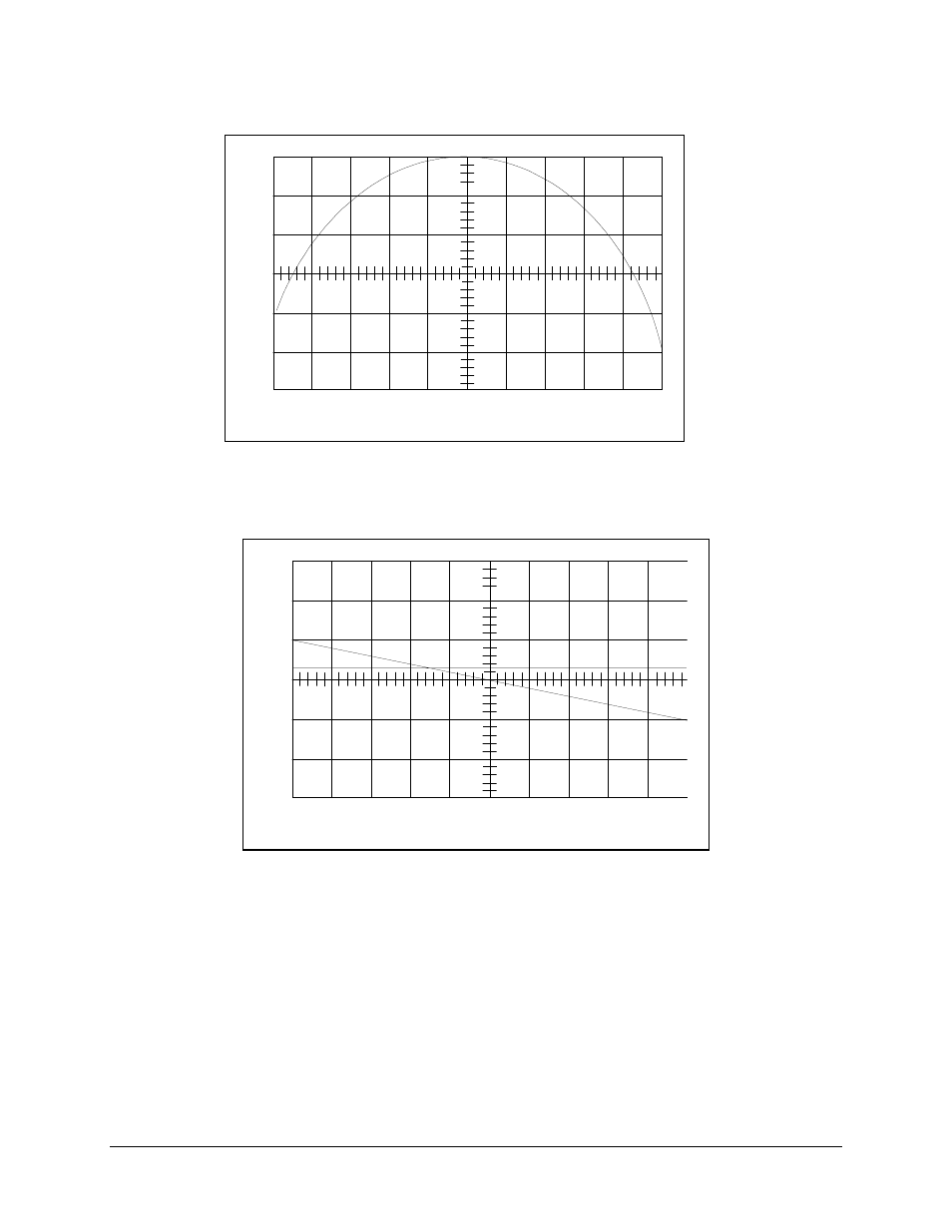
Figure Chapter 3-23. Shifted Equalizer Delay Characteristic
DELA
Y
(NS)
IF FREQUENCY (MHz)
Figure Chapter 3-24. Resultant Composite Delay Characteristic
Figure Chapter 3-25 through Figure Chapter 3-27 illustrates what would happen to the
composite delay shape if the equalizer had more delay than the satellite transponder. The
inverse composite delay characteristics would result if the equalizer had less delay than
the satellite transponder. The direction of the curve determines how the equalizer is to be
adjusted. In this instance, equalizer sections tuned to frequencies above 70 MHz must be
adjusted to even higher frequencies.
Advertising