Figure chapter 3-5 – Comtech EF Data EQ90 Series User Manual
Page 33
Advertising
EQ90 Amplitude Equalizer
Operation
Rev. 2
3-9
MLA
TX
IF
IN
IF
OUT
70 TO 140 MHz
-15 dBm
EQUALIZER
MODULE
EQUALIZER
MLA
TX
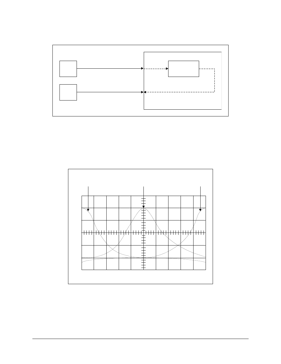
Figure Chapter 3-4. Alignment Setup
Figure Chapter 3-5 through Figure Chapter 3-20 depict oscilloscope patterns as displayed
on a Microwave Link Analyzer (MLA).
Refer to Figure Chapter 3-5 for a typical MLA display.
C MAX
DEL
A
Y
(NS)
CENTER
FREQUENCY
IF FREQUENCY (MHz)
C MIN
Figure Chapter 3-5. Effect on Delay of Varying C Switch
Advertising
See also other documents in the category Comtech EF Data Equipment:
- CDD-880 (124 pages)
- CDM-800 (130 pages)
- ODMR-840 (184 pages)
- CDM-750 (302 pages)
- CDM-840 (244 pages)
- SLM-5650A (420 pages)
- CTOG-250 (236 pages)
- CDM-700 (256 pages)
- CDM-760 (416 pages)
- CDM-710G (246 pages)
- CDM-600/600L (278 pages)
- CDMR-570L (512 pages)
- CDM-625 (684 pages)
- CDM-625A (756 pages)
- CDD-564A (240 pages)
- CDD-564L (254 pages)
- CLO-10 (134 pages)
- MCED-100 (96 pages)
- CDMR-570AL (618 pages)
- CDM-600 LDPC (2 pages)
- BUC Power Supply Ground Cable (2 pages)
- MPP70 Hardware Kit for CDM-570L (4 pages)
- MPP50 Hardware Kit for CDM-570L (4 pages)
- CDM-625 DC-AC Conversion (4 pages)
- CDM-625 DC-AC Conversion with IP Packet Processor (4 pages)
- DMDVR20 LBST Rev 1.1 (117 pages)
- DMD2050E (212 pages)
- DMD-2050 (342 pages)
- DMD1050 (188 pages)
- OM20 (220 pages)
- QAM256 (87 pages)
- DD240XR Rev Е (121 pages)
- MM200 ASI Field (5 pages)
- DM240-DVB (196 pages)
- MM200 (192 pages)
- CRS-150 (78 pages)
- CRS-280L (64 pages)
- CRS-170A (172 pages)
- CRS-180 (136 pages)
- SMS-301 (124 pages)
- CiM-25/8000 (186 pages)
- CiM-25 (26 pages)
- CRS-500 (218 pages)
- CRS-311 (196 pages)
- CIC-20 LVDS to HSSI (26 pages)