System integration alignment procedure, 4 system integration alignment procedure – Comtech EF Data EQ90 Series User Manual
Page 41
EQ90 Amplitude Equalizer
Operation
Rev. 2
3-17
3.4.4
System Integration Alignment Procedure
Note: The following description assumes that the equalizer has been tuned to the inverse
of the satellite transponder group delay characteristic.
The last stage of the adjustment procedure involves matching the delay characteristic of
the satellite transponder and that of the equalizer. Final adjustments of the equalizer may
be required to remove residual linear, parabolic and/or delay ripple components.
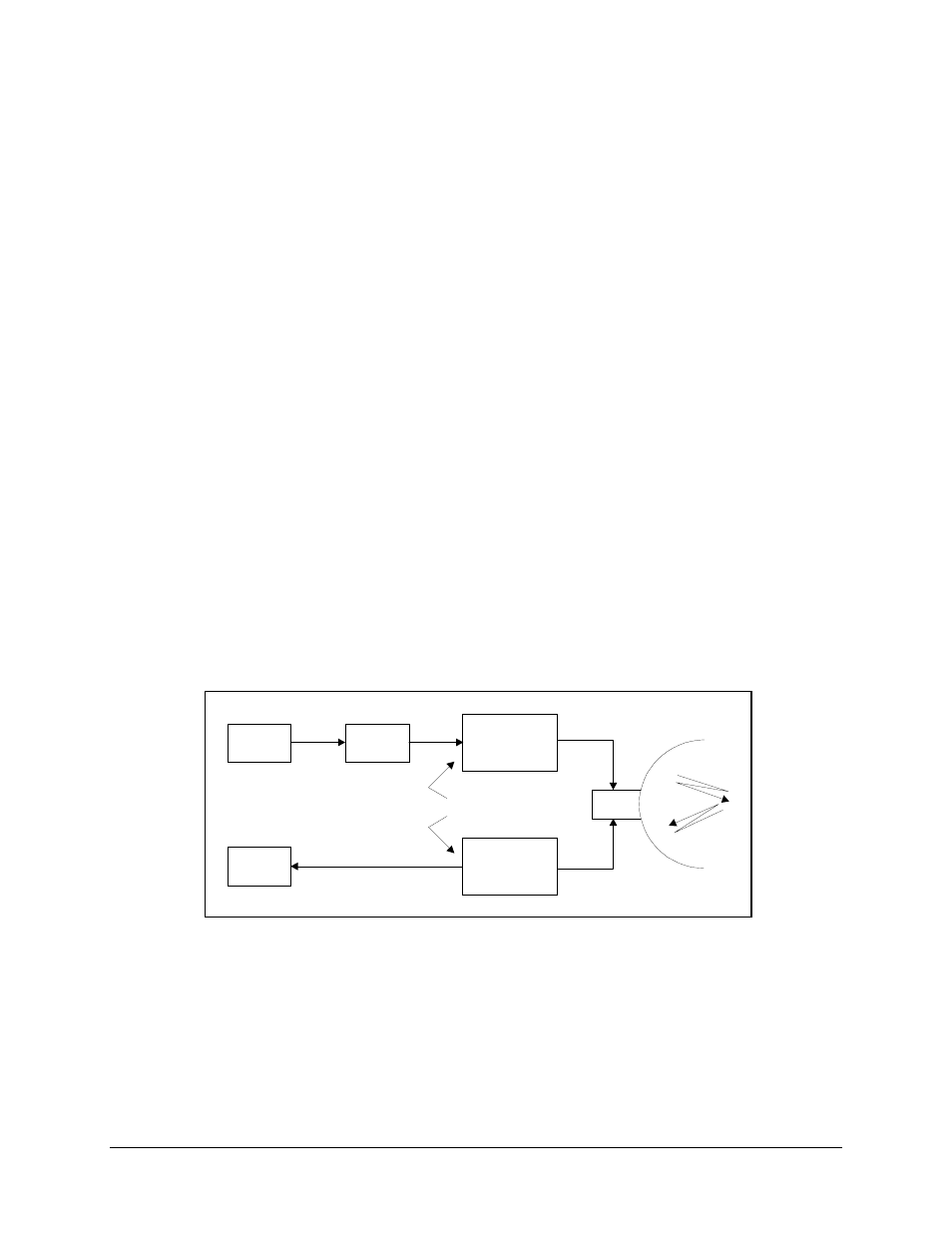
A typical test setup block diagram required for this process is shown in Figure Chapter 3-
15.
Figure Chapter 3-16 shows a typical ideal full transponder delay characteristic. The
equalizer must have an inverse delay characteristic as shown in Figure Chapter 3-17. The
two delay characteristics when combined would ideally provide the composite delay
result shown in Figure Chapter 3-18.
In actual practice, the transponder delay characteristic is rarely symmetrical or smooth as
shown in Figure Chapter 3-16 and it is rare for any two-satellite transponder to have the
same delay shape and magnitude. If the RF carrier remains at the transponder center
frequency, as the IF bandwidths of the carrier in use narrows, the transponder group
delay will be progressively reduced. However, it is typical that narrow bandwidth RF
carriers will be shifted towards one of the two transponder band edges.
MLA
TX
MLA
TX
UUT
U/C, IPA
IFL, HPA
RF, MUX
70
MHz
OR
140
MHz
LNA, IFL
D/C
ANT
Figure Chapter 3-15. System Integration Alignment Test Setup