Comtech EF Data EQ90 Series User Manual
Page 30
Operation
EQ90 Amplitude Equalizer
3-6
Rev. 2
R
R
EQ6
C
IN
OUT
DELAY
L
R
R
EQ7
C
IN
OUT
DELAY
L
R
R
SLP
ADJ
BYPASS
LVL MON
GAIN
ADJ
EQ10
C
IN
OUT
DELAY
L
R
R
EQ9
C
IN
OUT
DELAY
L
R
R
EQ8
C
IN
OUT
DELAY
L
R
R
EQ5
C
IN
OUT
DELAY
L
R
R
EQ4
C
IN
OUT
DELAY
L
R
R
EQ2
C
IN
OUT
DELAY
L
R
R
EQ1
C
2
3
4
5
6
8
7
1
IN
OUT
DELAY
L
R
R
EQ3
C
IN
OUT
DELAY
L
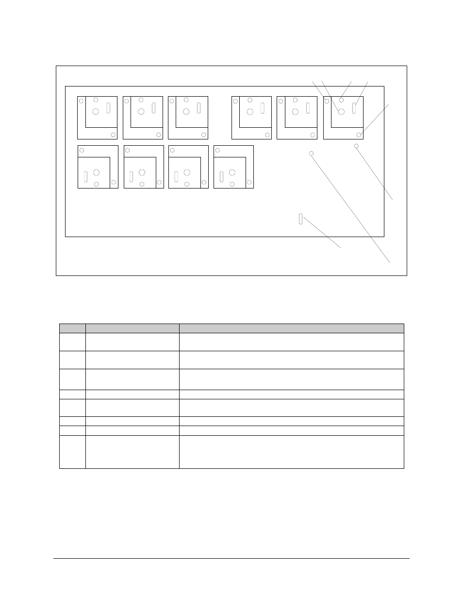
Figure Chapter 3-3. Equalizer Module
Table Chapter 3-3. Equalizer Module Control Functions
Item
Nomenclature
Function
1
R Switch
Used to adjust the amplitude response.
(Refer to Figure Chapter 3-7 for the signal pattern.)
2
L Switch
Used to adjust the delay peak magnitude.
(Refer to Figure Chapter 3-6 f or the signal pattern.)
3
C Switch
Used to adjust the delay peak center frequency. (Refer to Figure Chapter 3-5
for the signal pattern.)
4
IN/OUT Switch
Used to insert an equalizer delay section to, or remove from, the signal path.
5
R Switch
Used to adjust the amplitude response. (Refer to Figure Chapter 3-8 for the
signal pattern.)
6
GAIN ADJ Potentiometer
Used to set the IF output signal gain level (nominally 15 dB).
7
SLP ADJ Potentiometer
Used to provide
±
3 dB amplitude slope equalization.
8
BYPASS/LVL MON Switch
Used to activate the IF output signal level monitoring function. The minimum
signal level required to avoid an alarm condition is -20 dB. In the BYPASS
position, the signal level is not monitored. However, a power supply failure
will result in an alarm condition.