Daktronics AB-1600-1.5,2.5 User Manual
Page 12
Introduction
1-4
General Display Definitions
Controller Computer: The computer that controls what you see on the display. Information is
sent from the controller computer to the display controller through fiber optic cable.
Display Controller: A general term used to describe the device housed either inside or outside
the display that receives signal from the controller computer. This display will use either a line
receiver or a data distributor as a display controller.
Fan Controller Enclosure: An assembly found within the display that receives information from
the cooling fans. The fan controller card within the enclosure provides power to the fans and
monitors the fans for proper operation. If a fan failure is detected, the fan control circuit sends a
signal to the data distributor telling it to blank the display. This prevents the display from over-
heating. If the display remains blanked for 30 minutes, the data distributor or line receiver sends a
signal to the fan control circuits, turning the fans off. This extends the life of the fans and filters.
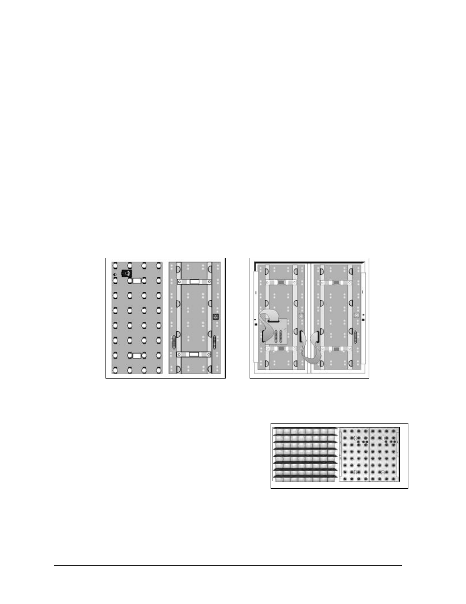
Lampbank: A circuit board consisting of an array of lamps eight pixels high by four pixels wide.
Two lampbanks mount to the rear of each lens/reflector assembly as seen in Figure 5. A single
lampbank, front and back, is illustrated in Figure 6. If necessary, a lampbank can be easily
removed from the lens/reflector assembly.
Lampbank Test Fixture: An optional unit designed to test a single lampbank separately from the
display.
Lens/Reflector Assembly: Consists of reflectors, lenses
and louvers. A lens/reflector assembly is eight lenses high
by eight lenses wide and is easily removable for
maintenance. Figure 7 illustrates the front and back of a
lens/reflector assembly. Two lampbanks mount on the rear
of this assembly.
Light Detector: The light detector is a device that senses ambient light levels. The light detector
and the controller operate together to dim the display when maximum lamp brightness is not
required. This saves energy and extends lamp life. Refer to ED-9490 and Drawing A-79768 in
Appendix C for light detector installation information.
Figure 5: Two lampbanks on the
back of a lens/reflector assembly
Figure 6: Lampbank, Front and Back
Figure 7: Lens/reflector Assembly, Front
and Back