Daktronics AB-1600-1.5,2.5 User Manual
Page 60
Maintenance & Troubleshooting
4-16
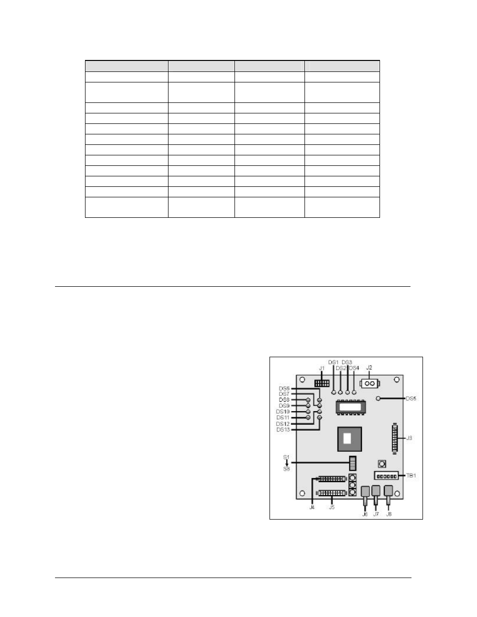
The following table describes the function of each LED indicator on the fan controller card.
LED indicator
LED – On
LED – Off
LED – Blinking
DS 1 Power
Power on
Power off
–
DS 2 Section
Status
Section good
Section failure
–
DS 3 Fan Power
Fan power on
Fan power off
–
DS 4 Fan 1 Status
Fan good
Fan not present
Fan failure
DS 5 Fan 2 Status
Fan good
Fan not present
Fan failure
DS 6 Fan 3 Status
Fan good
Fan not present
Fan failure
DS 7 Fan 4 Status
Fan good
Fan not present
Fan failure
DS 8 Fan 5 Status
Fan good
Fan not present
Fan failure
DS 9 Fan 6 Status
Fan good
Fan not present
Fan failure
DS 10 Fan 7 Status
Fan good
Fan not present
Fan failure
DS 11 Fan 8 Status
Fan good
Fan not present
Fan failure
DS 12 Thermostat
input
Thermostat
input good
Thermostat
input failure
–
To remove the fan controller card, remove all cables from jacks J2, J3 and J4, along with the white
power-in connector. After removing the four corner nuts, you should be able to remove the fan
controller card from its enclosure.
4.11 Troubleshooting the Line Receiver
Reference Drawings:
Line Receiver Settings, 32 & 40 High ......................................................Drawing A-109450
Line Receiver Settings, 64 & 72 High ......................................................Drawing A-109648
Line Receiver Settings, 48 & 56 High ......................................................Drawing A-110166
Remember, the display will have either a line receiver or a
data distributor. For a general description of both, refer to
Section 1.2 Display Overview.
To access the line receiver, refer to Section 4.3. Refer to
drawings in Appendix A for the location of the line
receiver in your display.
On the following page is a description of each LED
indicator on the line receiver board.
Figure 58: Line Receiver Board