Daktronics AB-1600-1.5,2.5 User Manual
Page 56
Maintenance & Troubleshooting
4-12
Complete the following steps to replace a lampbank.
1. Place the lampbank on the lens/reflector assembly. The white power connector (J1) should be to
the right side (rear view).
2. Press down upon each latch bracket until both the latch arms on each latch snap into position.
3. Reconnect the two lampbanks on the lens/reflector assembly with the ribbon cable.
4.
Put the lens/reflector back into the display cabinet as explained in 4.6.
In the event a lamp socket needs to be replaced on a lampbank, complete the following steps in a
static -free environment.
1. Unsolder the two contacts of the socket.
2. Carefully pull the socket from the lampbank. Take care not to damage the pad or lift the trace.
3. Insert the new socket and solder in place.
Clean the area of solder residue and apply conformal coating to the circuit board to protect against
moisture damage. Use PC-101 protective coating for circuit boards (or equivalent). SE-1003 is the
Daktronics part number for such coating.
4.7
Display Ventilation Summary
Excessive heat shortens the life of all electrical components, including
lamps. Daktronics 1600 series large matrix displays depend on a three-part
ventilation system to prevent heat buildup within the cabinet.
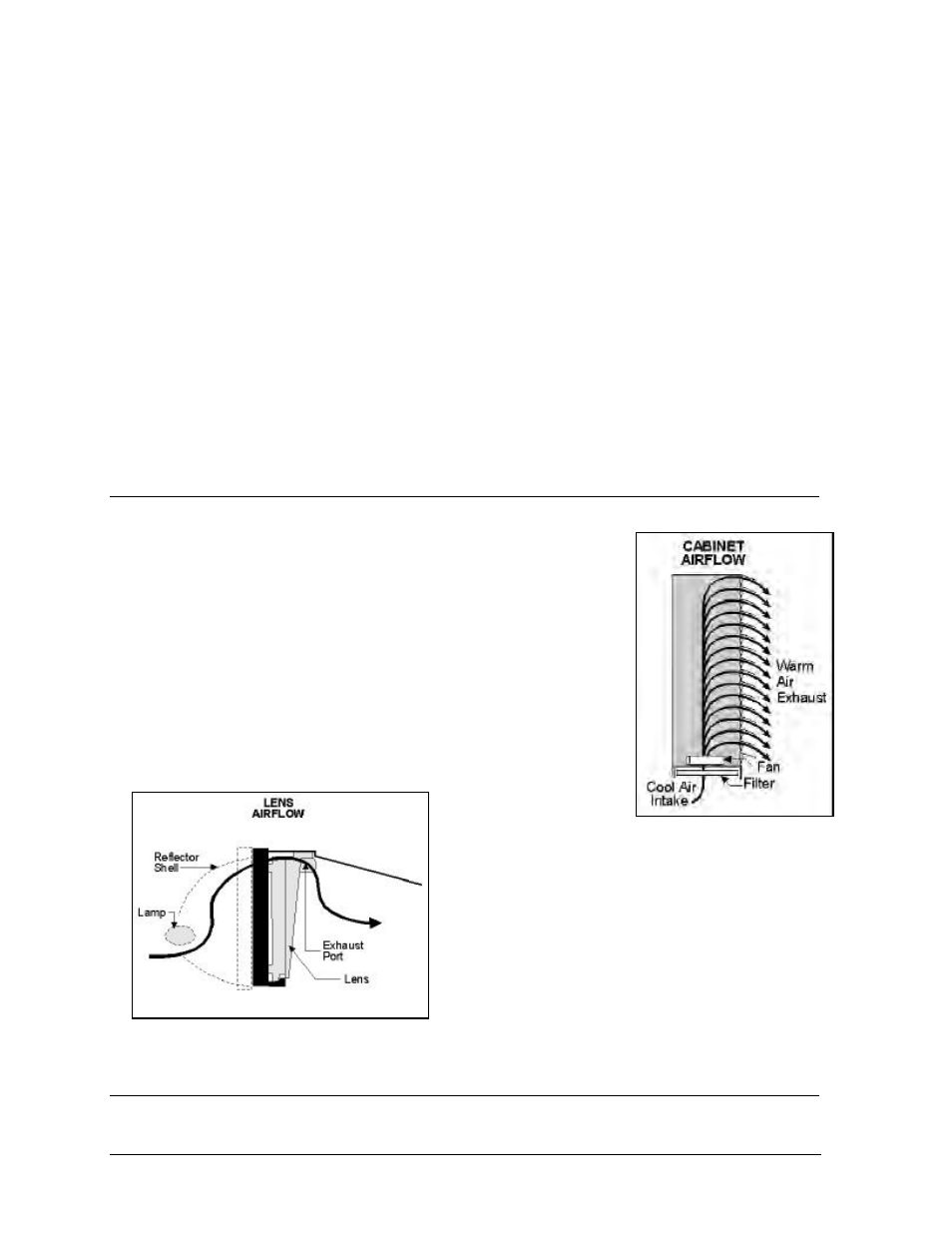
The three critical parts of the ventilation system are the filters, fans and
lenses. The fans draw cooler air from outside the display through the
filters and into the display. This incoming air forces warm air already in
the cabinet to exit through the lenses on the face of the display, as
illustrated in Figure 52. Each lens has an exhaust port near the top to
allow for airflow. Before the air exits through the lenses, it passes past the
lamps, cooling them in the process. This maximizes the life of the lamps.
Figure 53 illustrates this lens airflow process.
In addition, the display controllers in 1600 series large
matrix displays will turn off power to the fans if they
sense the display has been blank for 30 minutes. This
action is completed through the relay in the fan control
enclosure. This extends the life of both the fans and
the filters. The display controller will start the fans
automatically when the display is put into use.
4.8
Fan Filters
Shrouds are provided on the rear of the display to house the fan filters and shed rain. Filters must be
Figure 52: Cabinet Airflow
Figure 53: Lens Airflow