Daktronics AB-1600-1.5,2.5 User Manual
Page 20
Mechanical Installation
2-4
1. Bring the first lower section, Section 1, of the display into position and weld the upper and lower
clip angles to the upper and lower horizontal tubing. Pay close attention to this first display section.
Ensure it is both vertically and horizontally straight, as all other sections will be based on this
section’s position.
2. If an additional section is to be placed beside the first section, apply a
3
/
16
-inch (5 mm) bead of
silicone around all interconnect holes and around the entire perimeter of the side of the section
frames.
3. Lift the next section on the lower section row, Section 2, into position beside the first section
mounted. All lower display sections should be installed first.
4. Bolt the lower display sections together vertically. A detailed illustration of section bolting is found
in Drawing A-116653 in Appendix B. Adjust the section’s clip angles, if needed, and weld to the
upper and lower horizontal tubing.
5. If mounting additional sections to the top of the
bottom sections, remove the lift eyebolts from
the bottom sections and fill these holes
completely with silicone. Apply a
3
/
16
-inch (5
mm) bead of silicone around all interconnect
holes and around the entire perimeter of the top
of the bottom section frames. Bring the first top
section, Section 3, into position.
6. Bolt the upper section to the lower section.
Adjust the upper section clip angles, if needed,
and weld to the upper and lower horizontal
tubing. Apply a
3
/
16
-inch (5 mm) bead of
silicone around all interconnect holes and
around the entire perimeter of the side of the
section frame. Stack the next upper display
section (Section 4) onto the next lower section
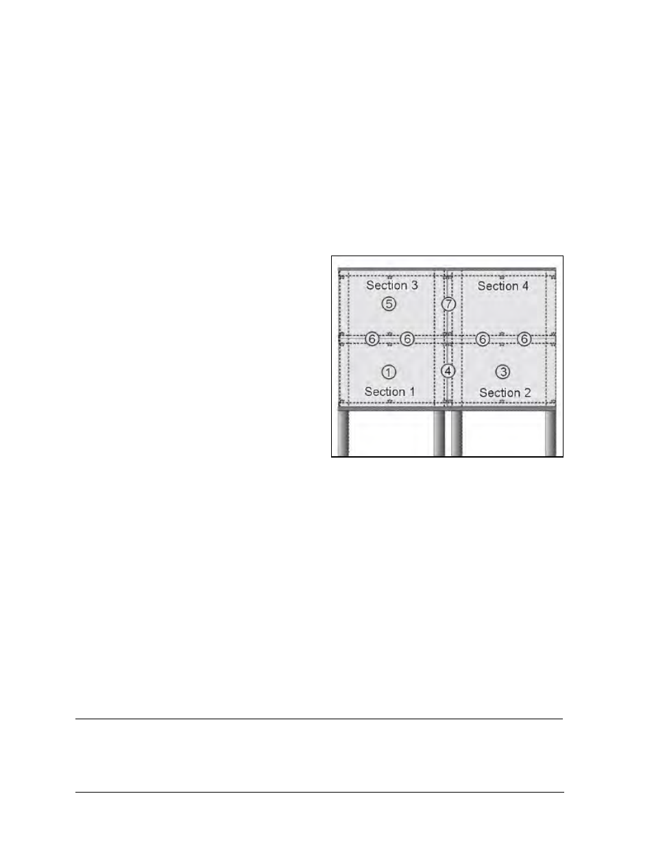
and bolt them together horizontally.
7. Bolt the top sections together vertically. Adjust the section’s clip angles, if needed, and weld to the
upper and lower horizontal tubing.
Height variation for any four-foot horizontal section (1219 mm) must not exceed ¼-inch (6.4
mm).
Bolt display sections together vertically and horizontally.
After completing installation, carefully inspect the display for any holes that may allow water to seep
into the display. Seal the any holes with silicone sealant.
If the eye bolts on the upper most sections (or the top of the display cabinet) have been removed from
the display, plug the holes with bolts and the rubber-sealing washer that was removed with the eyebolt.
2.5
Full Cabinet Display Mounting
Reference Drawing:
MTG Example, Full Matrix ........................................................................Drawing A-123964
Figure 20: Sectional Mounting Method