Daktronics AB-1600-1.5,2.5 User Manual
Page 55
Maintenance & Troubleshooting
4-11
7. Turn fixture power OFF.
8. Replace all lamps with Daktronics approved lamps of the same wattage.
9. Turn test fixture power on and check if all lamps light up. If lamps don’t light properly, check
the troubleshooting section of the maintenance manual.
10. Test the lampbank output.
11. Unplug the lampbank and return it to the display.
4.6
Lampbanks
Note that different 8x4 lampbank part numbers are
used within data distributor controlled displays.
Refer to Sections 4.21 and 4.22 for the correct
replacement parts.
Complete the following steps to remove a
lampbank from a lens/reflector assembly.
1. If the display is front accessible only, remove
the appropriate lens/reflector assembly as
explained in Section 4.3. If the display is rear
accessible, the lens/reflector assembly may not
need to be removed in order to remove a
lampbank.
2. Disconnect the ribbon cable connecting the two
lampbanks.
3. Each lampbank is held to the lens/reflector
assembly by two plastic latches. One latch at a
time, squeeze the latch arms together
and pull that end of the lampbank up
past the latch. Refer to Figure 51.
4. Pull the lampbank from the
lens/reflector assembly.
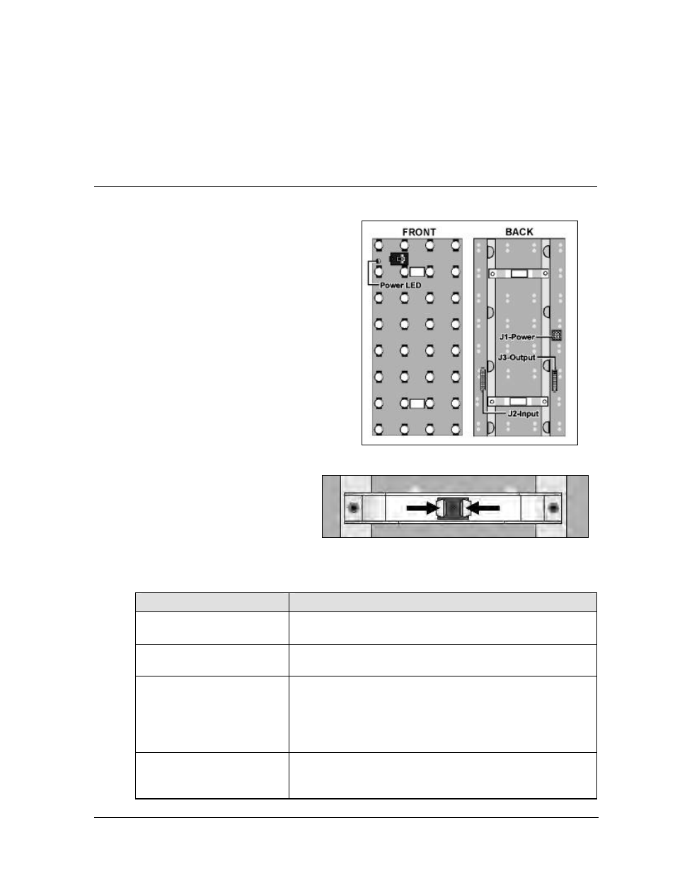
The functions of the labeled lampbank components in Figure 50 are explained in the following table.
Component
Function
Power LED
A lit LED indicates the lampbank is receiving its
operational voltage of 5 VDC.
J1-Power
Power from a transformer enters the lampbank at this
connector.
J2-Input
Signal enters the lampbank at this connector from any
of the following sources:
•
From a vertical shift board if it is the left-most
lampbank in any row (front view).
•
From the previous lampbank in that row.
J3-Output
Signal exits the lampbank at this connector and is
passed to the next lampbank in that row. This
connector is not used on the last lampbank in any row.
Figure 50: Lampbank Components
Figure 51: Lampbank Latch