Daktronics AB-1600-1.5,2.5 User Manual
Page 19
Mechanical Installation
2-3
•
The mounting structure will provide a straight and square frame for mounting the display. Height
variation in any four-foot (122 cm) horizontal section may not exceed ¼ inch (6.4 mm).
•
The mounting structure will not give way at any unsupported points after the display is mounted.
In addition, keep the following critical points in mind.
•
The bottom of the display must be continuously supported along its length. The bottom display
attachment must support the weight of the display and any additional weight caused by ice, snow,
etc., plus half the wind load.
•
The top of the display must resist overturning and half the wind load.
•
If the display was shipped in sections, and the sections must be removed from the trailer prior to
installation, do not sit the sections directly on the ground. Place them on spacers at least two inches
high to prevent module damage.
•
Ensure the drain holes in the bottom of the display or the bottom angle of the display is not
obstructed by the mounting structure. If this is the case,
3
/
8
-inch (9.5mm) drain holes must be
drilled through the mounting structure in the same location as the original holes. Be sure to maintain
a minimum of ½-inch (13 mm) clearance between all bottom drain openings in the base of the sign
and the mounting structure.
•
Depending on display design, it may be necessary to jump ribbon cable from the last driver board in
one section row to the first driver board in the section beside it. If this is the case, do not crush the
ribbon cables between the display sections.
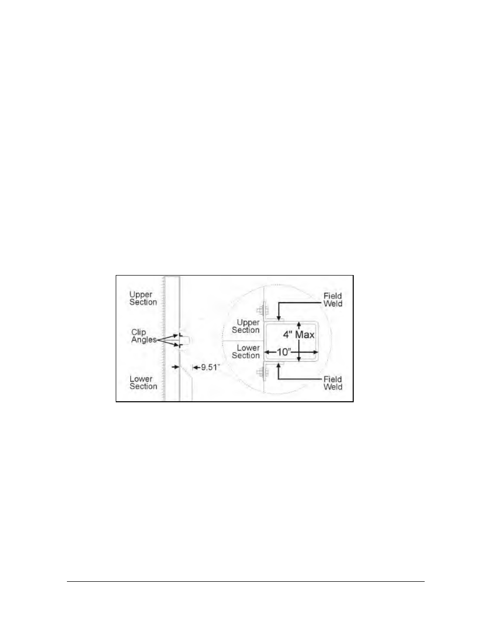
Figure 19 illustrates one possible mounting method for a large matrix display. Refer to Drawing A-
116653 in Appendix B for details. Figure 19 shows two display sections being welded to a piece of
horizontal tubing that was attached to a support structure by the customer/subcontractor. A cabinet
display could be attached in a simila r manner.
Figure 20 and the steps below provide an example of how a sectional display might be mounted using
the horizontal tubing method illustrated in Figure 19. The number of sections in a display may vary.
The purpose of the following information is to provide general guidance in mounting the individual
sections to a support structure. Refer to Drawing A-116653 in Appendix B for details.
The numbered areas in Figure 20 correspond to the numbers of the following steps.
Figure 19: Outdoor Mounting Method Example (Horizontal Tubing)