Hardware installation power connectors – DFI AR100-DR User Manual
Page 39
39
2
Hardware Installation
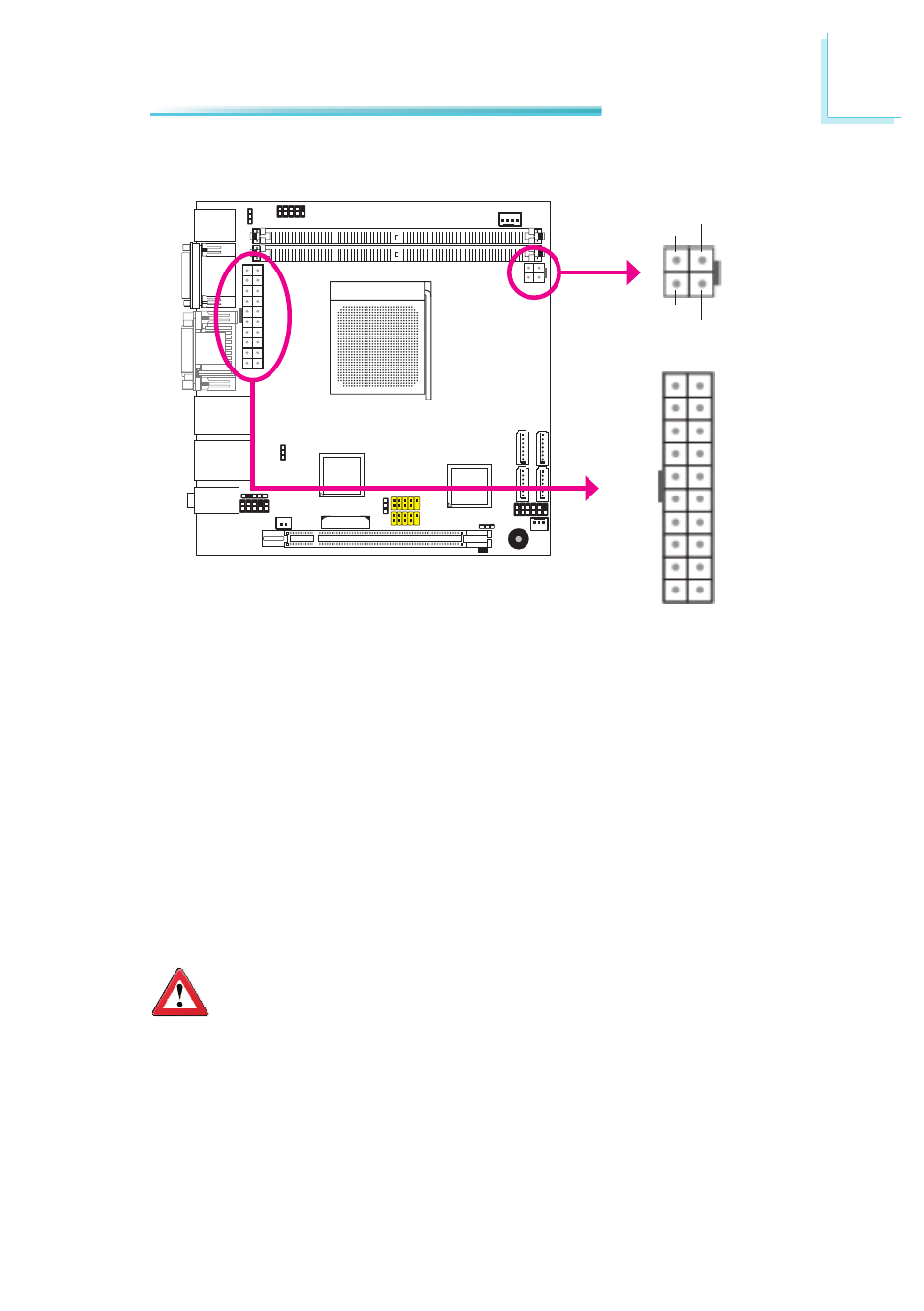
Power Connectors
2
3
Ground
Ground
+12V
+12V
4
1
+12V
10
1
20
11
+5V
+5V
+5V
+5V
PW-OK
5VSB
3.3V
3.3V
3.3V
-12V
Ground
Ground
Ground
Ground
Ground
Ground
Ground
PS-ON
-5V
Use a power supply that complies with the ATX12V Power Supply Design Guide
Version 2.0. An ATX12V power supply unit has a standard 20-pin ATX main power
connector that must be inserted into the 20-pin connector. The 4-pin +12V power
connector enables the delivery of more +12VDC current to the processor’s Volt-
age Regulator Module (VRM).
The power connectors from the power supply unit are designed to fit the 20-pin
and 4-pin connectors in only one orientation. Make sure to find the proper orien-
tation before plugging the connectors.
The system board requires a minimum of 300 Watt power supply to operate. Your
system configuration (CPU power, amount of memory, add-in cards, peripherals,
etc.) may exceed the minimum power requirement. To ensure that adequate
power is provided, we strongly recommend that you use a minimum of 400 Watt
(or greater) power supply.
Important:
Insufficient power supplied to the system may result in instability or
the add-in boards and peripherals not functioning properly. Calculating
the system’s approximate power usage is important to ensure that the
power supply meets the system’s consumption requirements.