Multiplayer - mounting, Multiplayer – ams configuration examples – Digital Alert Systems DASAMS User Manual
Page 5
Digital Alert Systems
AMS Installation / Operation & Integration Guide
Revision 1.1
Page 5 of 28
Step 1. MultiPlayer — Installation and initial configuration
The Digital Alert Systems MultiPlayer (model DASMP) is uniquely designed four-channel (designated as Ports 1 thru 4) audio
player and program switcher. The MultiPlayer works in conjunction with the AMC to provide independent audio playout for up to
four discrete channels whose particular operating attributes are defined in the AMC. The four independent ports can be
configured for mono-analog or stereo AES and ports can be “bonded” or grouped together to create multi-channel audio
configurations described below. The MultiPlayer’s flexible design allows it to be configured to use its internal switching or
originate the audio signal(s) for switching or embedding by downstream devices, including independent GPO’s to trigger these
devices. The MultiPlayer features automatic program bypass in the event of power fail thus assuring the program input for any
port is automatically routed to the program output of the same port if there is loss of power or power supply failure.
For clarity the term Audio Signal refers to the physical nature of the signal i.e. (AES) digital audio or analog, while Audio Type
denotes the action that will be applied to the signal during playback.
MultiPlayer - Mounting
The MultiPlayer manages the audio and contact closure wiring; therefore to facilitate ease of wiring it should be placed in close
proximity to audio signal sources and control points. The unit is attached to a 19” EIA equipment rack using the standard
mounting holes on the front panel. Mounting screws are included in the shipping box.
MultiPlayer – AMS Configuration Examples
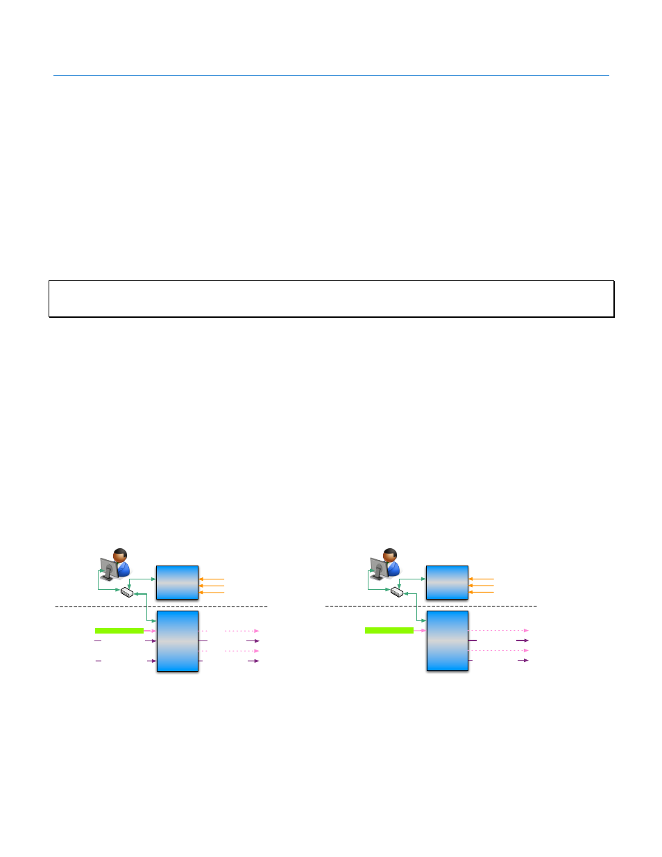
The Multiplayer features four Ports, each having an independent audio switch, four (4) GPI’s, and two (2) GPO’s. Based on the
required number of audio channels for the application each port may be used and configured in a different manner. Playback
control PLAY/PAUSE/STOP can be independently managed per port, however in the AMS application the incoming data is the
same for all ports and therefore creates the same audio file which is loaded into each channel.
For simplicity, it may be a good idea to wire the station’s Main program audio through Port 1 and the associated SAP channel on
Port 2. This is by no means the only configuration as there are a variety of ways the MultiPlayer and AMC can be configured to
manage different signal and source scenarios.
Local&Operator
Router
(Not&Included)
DAS&AMC
Audio&
Message&
Controller&
Main&Program&Audio
(Stereo&Analog&or&AES)
Secondary&Audio&Program
(Stereo&Analog&or&AES)
Main&Program&Audio&
(Stereo&Analog&or&AES)
Secondary&Audio&Program
(Stereo&Analog&or&AES)
Playback&Triggers&(OpConal)
DAS&MP
MulCPlayer&
Main&GPO
SAP&GPO
Incoming&Data
(Serial,&XML,&etc.)
Data$Layer$
Signal$Layer$
MulCPlayer&used&for&signal&switching
Local&Operator
Router
(Not&Included)
DAS&AMC
Audio&
Message&
Controller&
Main&Program&Audio&
(Stereo&Analog&or&AES)
Secondary&Audio&Program
(Stereo&Analog&or&AES)
Playback&Triggers&(OpConal)
DAS&MP
MulCPlayer&
Main&GPO
SAP&GPO
Incoming&Data
(Serial,&XML,&etc.)
Data$Layer$
Signal$Layer$
MulCPlayer&used&as&source
To&downstream&devices,
e.g.&embedders,&etc.
Figure 5 AMS wired for program audio switching
Figure 4 AMS wired for audio origination, triggering downstream
devices