Multiplayer - audio connections, Multiplayer - gpi’s & gpo’s – Digital Alert Systems DASAMS User Manual
Page 6
Digital Alert Systems
AMS Installation / Operation & Integration Guide
Revision 1.1
Page 6 of 28
MultiPlayer - Wiring
MultiPlayer - Audio Connections
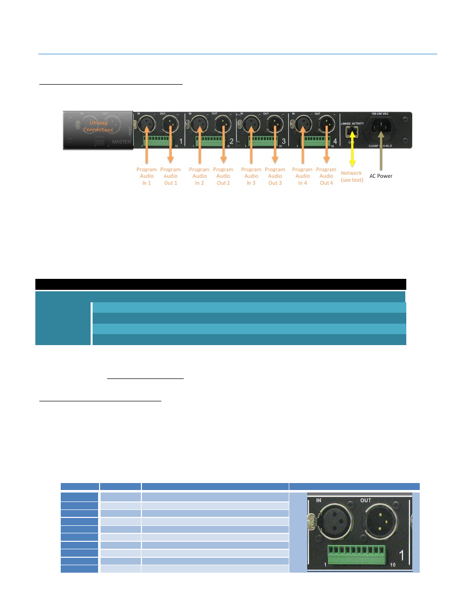
Audio connections are made to and from the MultiPlayer for each audio signal through the XLR connections on the ports labeled
1, 2, 3 & 4 as shown Figure 6. The AMS application does not require the Master Port and this port should remain unused.
Figure 6 MultiPlayer rear panel showing connections on Ports 1 -4. Master Port is not used
MultiPlayer ports are configured by selecting one of the standard audio signals then, under the AMC interface, selecting the
audio type. In this manner any port may be used for any audio signal as each port is configured for the audio type; Main, SAP,
or Preview in the AMC configuration. This allows mixing and matching any audio type across the four ports, which is especially
useful for stations with multiple Main and SAP channels.
Each of the MultiPlayer’s audio input/output ports can be configured to handle any one of these audio signals:
MultiPlayer Audio Signals (per port)
Designation
Description
AES3 AES digital with input (stereo pair) – locks to incoming AES signal for clock reference (Factory default)
ORIG AES digital without input (stereo pair) – uses internal reference clock, generates AES silence when not playing
ANALOG Analog mono – balanced audio input and output
SLAVE Analog stereo – combination – ties playout with prior port ANALOG channel, creating an analog stereo pair.
Table 2 MultiPlayer supported audio signals and designations
From the factory each port is preset for AES audio signal pass-thru. This may be changed to reflect AES origination or analog
mono as explained in Audio Port Configuration section below.
MultiPlayer - GPI’s & GPO’s
The MultiPlayer features four (4) General Purpose Inputs and two (2) General Purpose outputs per each port. The table and
picture below define the wiring locations and the corresponding labeling in the AMC. These ports match the AMC configuration
settings in the Configure > GPIO menu.
Notes:
1. GPO’s are not grounded, having two connections (Pins 1 and 2).
2. The terminal strip is removable to facilitate ease of wiring.
Port 1- 4
Connection
Applies to all ports 1, 2, 3 and 4
Port Connection Example (Port 1 shown)
Pin 1
GPO 1 Relay 1 Pin 1
Pin 2
GPO 2 Relay 2 Pin 1
Pin 3
GPI 1 Input 1
Pin 4
GPI 2 Input 2
Pin 5
GND Ground
Pin 6
GPO 1 Relay 1 Pin 2
Pin 7
GPI 3 Input 3
Pin 8
GND Ground
Pin 9
GPO 2 Relay 2 Pin 2
Pin 10
GPI 4 Input 4
Table 3 MultiPlayer GPI & GPO connections. Port 1 shown as example - other ports follow same configuration.