DR Power Z-Mower 19.5 HP Versa-Pro User Manual
Page 42
38 DR
®
VERSA-PRO
™
Z-MOWER
Align the Control Handles
1. Position the Speed Control Bar as close to the
Control Handles as possible and use it as a guide
to align the Control Handles.
2. Using a 9/16" Wrench, loosen the Nuts (Figure 27)
on the lower end of the Control Handles.
3. Line up the Control Handles so they are even with
each other and parallel with the Speed Control
Bar. Once aligned, tighten the Nuts securely.
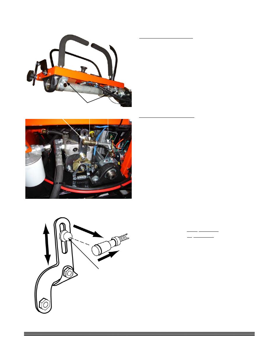
Equalize the Wheel Speeds
The Linkage Arm (Figure 28) settings on the Left and
Right Hydraulic Pumps should be the same to achieve
equal speed on both Wheels. Adjust the Left Wheel
speed to the Right Wheel speed as follows:
1. Remove the Left Steering Linkage Assembly by
sliding the spring loaded Collar (Figure 28) away
from the Joint and separating the Linkage from
the Ball Pivot (Figure 29).
2. Measure the location of the Ball Pivot in the Right
Hydro Control Arm.
3. Loosen the Nut holding the Left Ball Pivot to the
Hydro Control Arm.
4. Slide the Ball Pivot up or down, depending upon
the adjustment required to match the Right Hydro
Control Arm.
NOTE: Sliding the Ball down increases the speed;
sliding the ball up decreases the speed of the
Wheel.
5. Replace the Linkage Arm and test the alignment.
Repeat the procedure if necessary.
Figure 27
Control Handle Nuts
Figure 28
Figure 29
Collar
Ball Pivot,
Up or Down
Linkage Arm
Ball Pivot
Collar
Measure Ball
Pivot Location
in Arm Slot