Sa a a, A out port2, Same structure as port 1 – ESI MaXiO 032 User Manual
Page 33
MaXiO series
System Manual
33
: Monitoring enabled, signal will be mixed to mono
With the circle on the right, you can disable/enable monitoring for all input (or playback) channels
simultaneously.
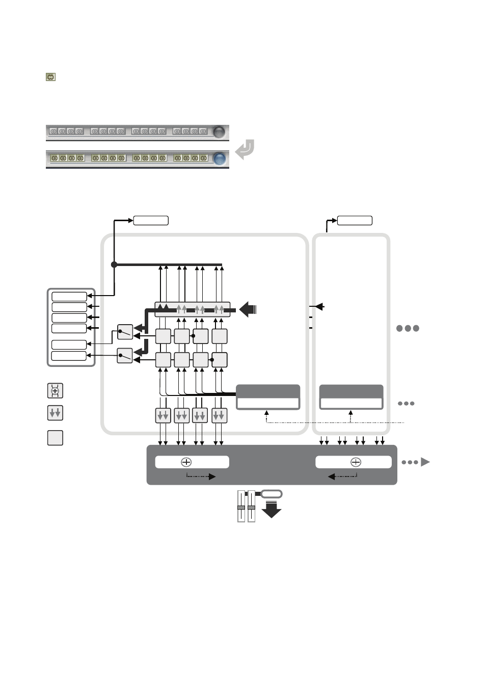
5.3.2 Master & Output signal path block diagram
5.4 MaXiO display section
The MaXiO display section on the right of the MaXiO Control Panel window is the location where
you can check and control the current status of the MaXiO PCI/PCIe host card. It is divided into
different sections that you can call by clicking on the specific button.
OUT PORT1
1/2 ` 3/4 5/6 7/8
S
S
S
A A
A
f
PLAY
DMA
1/2/3/4/5/6/7/8 ch.
Onboard S/PDIF Output
Ch. selection (CH5/6)
Onboard Analog Output
Ch. selection (CH7/8)
A
OUT PORT2
1/2 3/4 5/6 7/8
f
PLAY
DMA
8 ch. audio stream
E.D.I 1
M.D.I Connector
E.D.I Connector #1
9/10 11/12 13/14 15/16
same structure
as port 1
E.D.I 2
E.D.I Connector #2
MASTER OUT
From PC
Internal 64ch 32bit Digital Mixer
S
9/10/11/12/13/14/15/16 ch.
Master Output
Ch. selection
(CH1/2)
X X
X X
Mono MIX
Monitor ON
Monitor OFF
S
A
S/PDIF OUT
ANALOG OUT
M.D.I [1/4]
M.D.I [2/4]
M.D.I [3/4]
M.D.I [4/4]
Total 32ch DMA
at (max.) 192kHz