Flowserve Type R User Manual
Page 13
R and RX SLURRY Pump USER INSTRUCTIONS ENGLISH
71569242 03-11 (E)
Page 13 of 54
®
Oil lubrication is only available where the pump shaft is
horizontal. The bearings on frame 6 pumps (18R416)
can not be grease lubricated.
3.3.5 Bearing housing
For oil lubricated bearings, a bulls eye level gauge is
supplied. Constant level oilers can also be fitted. Two
grease nipples enable grease lubricated bearings to be
replenished between major service intervals.
3.3.6 Stuffing box housing
The stuffing box is a loose design and has a spigot
(rabbet) fit with the pump casing. The design enables a
number of sealing options to be fitted as well a wide
range of materials options.
3.3.7 Shaft seal
The mechanical seal(s), attached to the pump shaft,
seals the pumped liquid from the environment. Gland
packing may be fitted as an option. The “X” model is
fitted with an optional dynamic or expeller seal for
certain applications.
3.3.8 Driver
The driver is normally an electric motor. Due to the
hardness of the impeller the norm is to use multi-v-
belts. Different drive configurations may be fitted such
as internal combustion engines, turbines, hydraulic
motors etc driving via couplings, belts, gearboxes, drive
shafts etc.
3.3.9 Accessories
Accessories may be fitted when specified by the
customer.
3.4 Performance and operating limits
This product has been selected to meet the
specifications of your purchase order see section 1.5.
The following data is included as additional information
to help with your installation. It is typical, and factors
such as temperature, materials, and seal type may
influence this data. If required, a definitive statement
for your particular application can be obtained from
Flowserve.
3.4.1 Operating limits
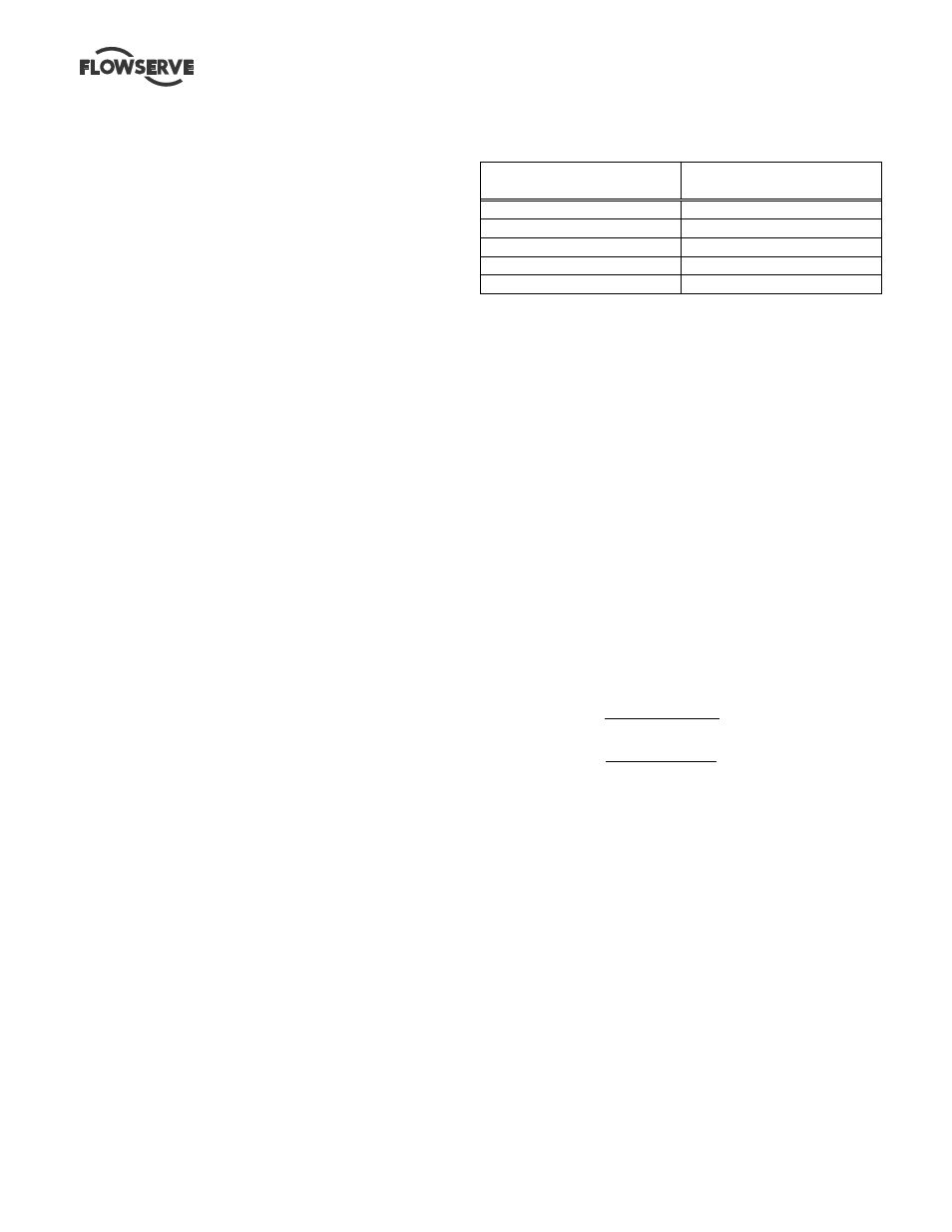
3.4.1.1 Temperature
Liner Materials
Maximum Operating
Temperature
Natural Rubber-soft
65ºC (150ºF)
Natural Rubber-Hard
80ºC (176ºF)
Nitrile 93ºC
(200ºF)
Neoprene 100ºC
(212ºF)
3.4.1.2 Pressure
The maximum working pressure will be 110 PSIG for all
sizes except for the 18R416 which will be 100 PSIG.
Vacuum service should be avoided due to potential of
rubber liner collapse.
3.4.2 Speed torque curves
To bring a centrifugal pump up to rated speed, the
driver must be capable of providing more torque at
each speed than required by the pump. The margin
between the available and required torque affects the
time it takes the unit to reach full speed. If the torque
required by the pump exceeds the torque capability of
the drive at any run-up speed, the unit will not
accelerate to full speed. Normally, this is not a problem
with standard induction or synchronous motors
provided the proper voltage is supplied at the motor.
For pumps started at shut valve conditions, 100 percent
full speed torque can be calculated by using the
formula:
Torque (Nm) = 9545 Shutoff Power (kW)
r/min
Torque (ft.lb) = 5250 Shutoff Power (hp)
r/min
Torque required by the pump at any other speed during
start-up can be determined from the curve above. Note
that the driver manufacturer usually bases 100 percent
torque on the design power of the driver and
consequently the speed-torque curves should be
plotted in torque units (e.g. Nm) instead of percentage
torque to avoid confusion.