Flowserve Type R User Manual
Page 43
R and RX SLURRY Pump USER INSTRUCTIONS ENGLISH
71569242 03-11 (E)
Page 43 of 56
flowserve.com
®
6.10.9 Casing
a) Install dowel pins in gland side casing.
b) Lift the suction side casing [1211] and assemble to
the gland side casing [1212].
c)
Pumps with 8” discharge and larger use spacers
between the casing halves. Install mounting
hardware.
spacers required for pumps 8” and larger
d) Secure into position. Ensure that the impeller is free
to rotate before torquing bolts.
e) Set the impeller front clearance in accordance with
instruction earlier in this section of the manual.
6.10.10 Shaft seal
6.10.10.1 Packing
a)
The two piece lantern ring [4134] must be installed
first for standard L5. Push the lantern ring and
previously installed packing. The ports in the lantern
ring do not need to be aligned with the inlet/outlet
ports.
b)
Insert one packing ring at a time into the stuffing box.
Push the packing as far as possible into the packing
bore.
Standard Packed Box Arrangement (frame 1-4)
c)
Install additional rings as required, staggering the
joints.
d)
Ensure that the shaft can be turned by hand.
e)
Install the remaining rings of packing, alternating the
joints.
It may not be possible to insert the last ring in
the box and still insert the gland. In this case, omit the
last ring of packing and install the gland.
The last ring of packing should be installed after the
pump has been in service and sufficient space is
available.
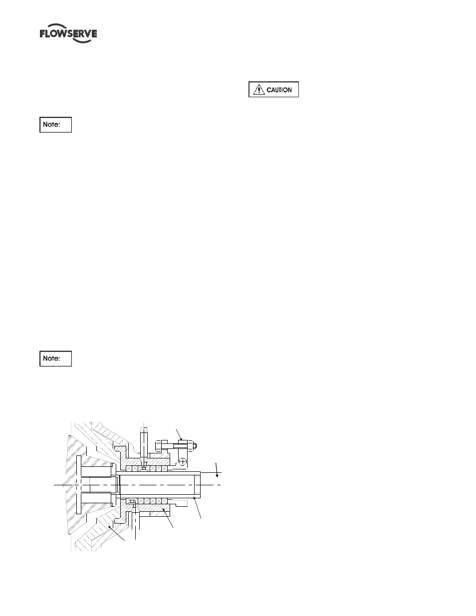
2L3 packing arrangement
L5 packing arrangement
Gland-17
Bushing-83
Nipple-127
Gland Side Casing-1D
Sleeve-14
Shaft -6
Standard Packed Box Arrangement (1.25R090)
f)
Install the gland halves [4120], tighten the gland nuts
[6580] only finger tight.
N
ew packing has to be run-in and it is
good practice to start the pump with the stuffing box
gland quite loose. Packing that is too tight in the box will
cause undue friction, creating heat which will glaze the
packing and possible score the shaft sleeves. To be
effective, the packing must remain soft and pliable. If
stuffing box friction is so great that the pump shaft cannot
be turned by hand, the box is not properly packed.
6.10.10.2 Mechanical seal
These details are specific to non-cartridge
seals therefore they may not apply. Refer to any
special instructions supplied with the mechanical seal.
a) Before the mechanical seal can be installed, the
pump must be assembled with the correct impeller
running clearances (ie: all assembly steps above). A
scribe mark is then placed on the circumference of
the sleeve to mark the end of the box. This mark is
used to locate the seal position referenced by the
mechanical seal drawing provided.
b) After scribing the sleeve, remove the rotating
element from the casing. Do not adjust the bearing
housing.
c) Remove the impeller [2200] and glandside casing
[1212]. Assemble the mechanical seal components,
including gland plates, gaskets and rotating parts
over the sleeve. Locate the seal relative to the
scribed markings on the shaft sleeve [2445] as
indicated by the seal manufacturers’ instruction.
d) Assemble the mechanical seal gland plate and
gasket and fasten using gland studs [6572]. Secure
with nuts [6580] and tighten each by hand. Further
tighten the nuts in accordance with Table in 6.6.
Rotate the shaft to ensure that it turns freely without
rubbing or binding.
e) Re-assemble the rotating element into the casing.
Do not adjust the thrust bearing housing.
f) Set the deflector [2540] at the line bearing cover
[3260] so that they do not contact when the shaft is
rotated. Lock in place with the setscrews provided.
6.10.11 Final assembly
a) Lift the assembled pump onto the baseplate and
position the casing feet over the tapped holes in the
baseplate.
b) On frame sizes 1 to 4, loosen the bolts that attach
the rear support foot [3134] to the bearing frame
[3130]. Level the unit and align with the piping.
Tighten the bolts attaching the casing feet to the
baseplate in accordance with Table 6.6 using for
tightening torques. Do not distort casing or frame.
c) Install the pump coupling or sheave as required.
d) Refer to Section 4, Installation and Section 5,