Flowserve Type R User Manual
Page 40
R and RX SLURRY Pump USER INSTRUCTIONS ENGLISH
71569242 03-11 (E)
Page 40 of 56
flowserve.com
®
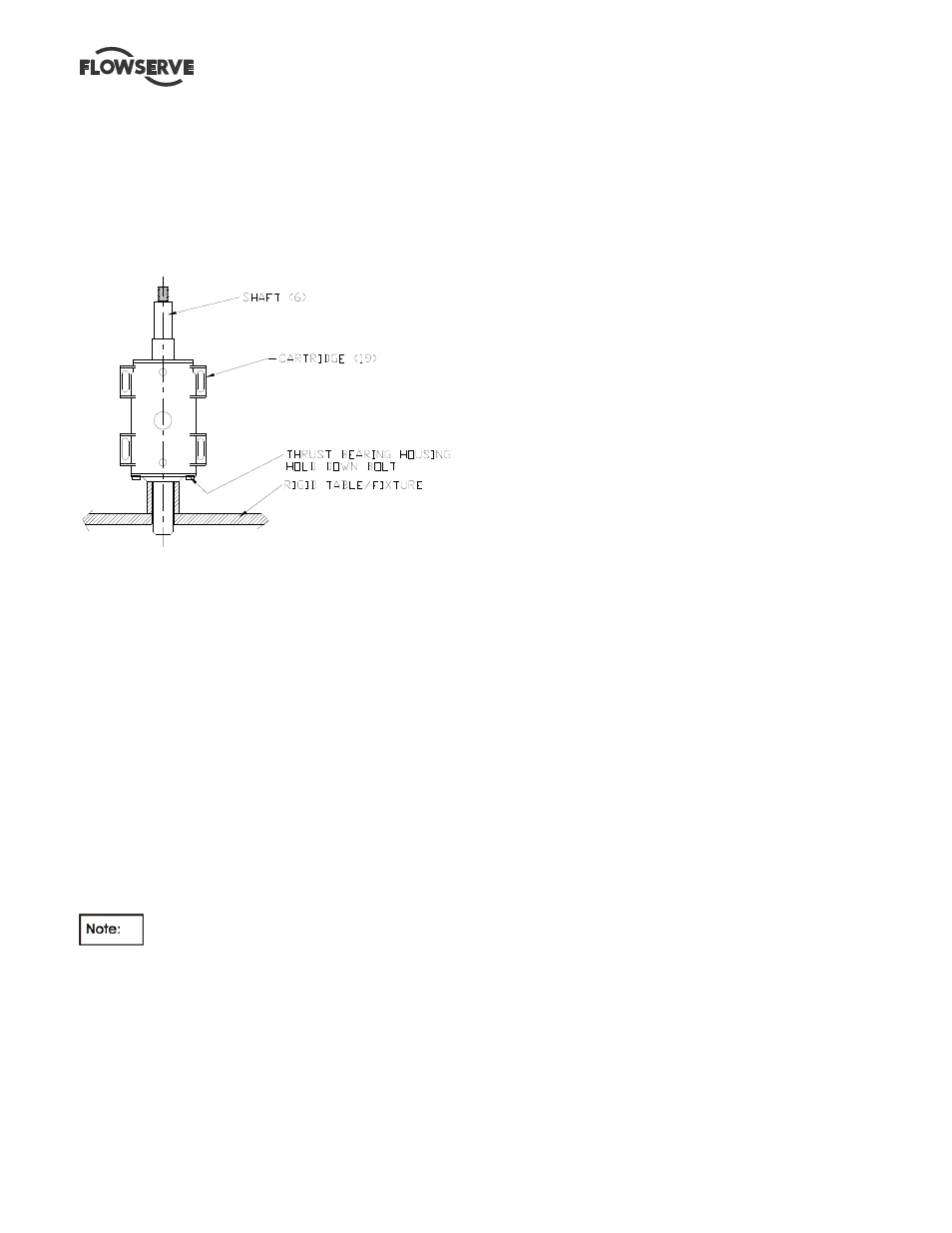
6.10.4.3 Frame 6
a) Place the shaft assembly in a vertical position with
the thrust bearing housing [3230] resting on the
flange face. The shaft should be supported in a
fixture for safety and to prevent damage. Access
to one hole in the thrust bearing housing [3230] is
required to attach one bolt.
b) Install the gasket [4590] onto the housing flange.
c) Lift the bearing cartridge [3130] vertically and
lower over the shaft assembly. Manually guide the
line bearing outer race into the bearing cartridge
bore. The thrust bearing housing [3230] and
cartridge [3130] are orientated to ensure that the
oil return slot in the thrust bearing housing [3230]
is properly located.
d) Install at least one thrust bearing housing to
bearing frame hold down capscrew complete with
lockwasher to prevent the assembly from coming
apart when lifting.
e) Install oil site gauge [3856] and plugs in side of
bearing cartridge [3130].
f) Place the bearing frame assembly into a
horizontal position and mount unto the pedestal
rails.
g) The pedestal rails have sets of holes that will be
used to lock the pedestal in position. The outer
holes will be used for initial installation.
As the pump wears in service and the
impeller is readjusted the inner holes will be exposed
and the hold-down bolts will have to be moved.
h)
Install the remaining hold down capscrews and
lockwashers into the bearing housing [3230].
i)
Install the cartridge hold down bolts with the
heavy plate washers but do not tighten.
j)
Install the adjusting screw [6576] between the ribs
of the bearing cartridge [3130]. The fixture may be
installed on either side of frame as convenient for
the installation.
6.10.5 Line Bearing Cover
6.10.5.1 Frames 1-4
a) Carefully install the lip seal [4300] in the line bearing
cover [3260] by pressing it squarely into the bore.
The primary sealing lip [spring loaded] on seal
should be installed facing the bearing. A small
amount of sealant may be applied on the O.D. of the
seal prior to its' installation.
b) Lubricate the o-ring [4610] and assemble into the
groove of the line bearing cover.
c) Assemble the line bearing cover [3260] over the
shaft and squarely into the bearing frame bore.
Fasten to the bearing frame with capscrews,
washers and hex nuts. Tighten firmly, but not
excessively.
d) Assemble the deflector [2540] loosely over the shaft
but do not tighten the setscrews.
e) Install the coupling key [6700] and tape to the shaft.
f) Rotate the shaft and check that run-out does not
exceed 0.050 mm (0.002 inch).
6.10.5.2 Frame 6
a) Install the lip seal [4300] into the line bearing
cover [3260].
b) Assemble the gasket [4590] onto the face of the
line bearing cover [3260].
c) Assemble the line bearing cover [3260] over the
shaft and squarely into the bearing frame bore.
Fasten to the bearing frame with capscrews,
washers and hex nuts. Tighten firmly but not
excessively.
d) Assemble the deflector [2540] with a slight gap
such that it does not rub when shaft is rotated.
e) Install the coupling key [6700] and tape to the
shaft.
f) Rotate the shaft and check that run-out does not
exceed 0.050 mm (0.002 inch).