Flowserve Type R User Manual
Page 42
R and RX SLURRY Pump USER INSTRUCTIONS ENGLISH
71569242 03-11 (E)
Page 42 of 56
flowserve.com
®
6.10.6.6 Optional expeller seal-frame 3 & 4
f) Assemble the stuffing box [4100] over the sleeve
[2445] and into the bearing frame [3130] register.
Orient the grease fitting to suit the installation. Note
that if the optional solid gland with lip seal design is
used, it must be installed first.
g) Install O-ring onto the expeller stuffing box
groove. Install expeller wearplate [1915] onto the
stuffing box.
Some units may be built with a 1 pc stuffing
box/wearplate. In this cause this step will be
eliminated.
h) Install the expeller [2250] over the shaft sleeve.
Expeller should seat against the sleeve shoulder
but be clear of the expeller wearplate [1915].
Adjust the shaft [2110] forward to ensure that the
expeller [2250] when installed will not bind against
the stuffing box head [4100].
i) Install gasket [4590] over expeller to face of
stuffing box [4100].
j) Install expeller housing [4110] to stuffing box
[4100], clamp in place.
6.10.6.7 All Expeller fitted Units
a) The face of the expeller housing [4110] has a
recess cut that seats against the gland side liner.
To assist with sealing apply a bead of silicone to
this recess.
b) Lift casing [1212] and liner and install over the
expeller housing [4110].
c) Secure to pedestal [3120].
6.10.7 Impeller Installation-all pumps
a) Install the impeller gasket [4590] on all pumps.
b) Install the impeller spacer [2460].
c) Due to the method of assembling the impeller, it is
recommended to smear the sleeve face and both
sides of the impeller spacer [2460] with a heavy
grease or a silicon sealant before assembling onto
the shaft which will help to hold the impeller spacer
in position during assembly.
d) Apply anti-seize compound to the shaft threads and
screw the impeller onto the shaft. For large sizes it
is more practical to hold impeller using a sling and
hoist and turn the shaft.
Failure to tighten the impeller [2200]
spacer [2460] securely against the sleeve may
cause serious damage to pump components.
The thread is designed so that during
operation the impeller will tend to tighten onto shaft.
Therefore a clockwise shaft rotation (looking from
coupling end) will screw impeller on.
e)
Release the thrust bearing housing hold down bolts
and tighten the jacking screws to pull the impeller
back to the stuffing box head [4100]. The stuffing
box head must not be rigidly clamped.
6.10.8 Suction Side Liner
6.10.8 1.25R090
a) Place casing [1211] on clean work surface with
the casing resting on the suction flange.
b) Lift liner in install into casing.
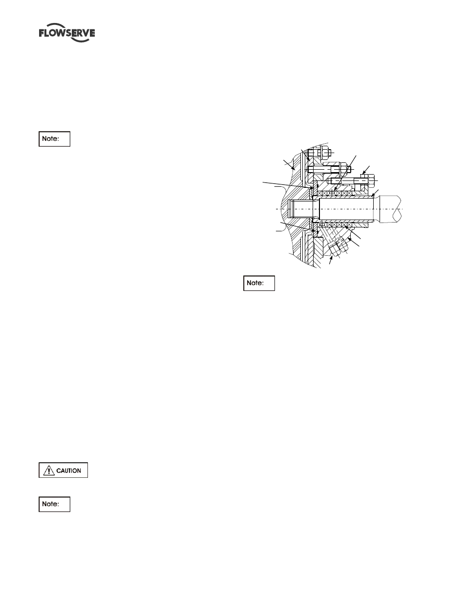
IMPELLER (2)
GLAND SIDE LINER (223)
4 LANTERN RING CONNECTIONS
2 FOR EACH PACKING ARRANGEMENT
SPLIT GLAND (17)
PROTECTOR PLATE
(185)
O-RING (89C)
SHAFT SLEEVE (14)
PACKING (13)
LANTERN RING (29)
STUFFING BOX (83)
OPTIONAL ARRANGEMENT (2L3)
RECOMMENDED ARRANGEMENT (L5)
The 1.25R090 does not use bolts to hold the
liner in place.
6.10.8.2 12R264 and 18R416 with 2 pc liner
a) Place the suction side liner [1916] for 2 pc liners on
12R264 and 18R416] on a clean work surface with
support plate (stud holes exposed)
b) Install the studs [6572] in the suction side liner
[1916.1] using Loctite grade A or equivalent.
c) Smear the suction nozzle and volute wall with a
liquid soap (do not use petroleum product as it
can swell some rubbers.
d) Lift suction side casing [1211] and install over liner
[1916]. The sealing lip of the suction nozzle must
be pried into position. Use a blunt pry bar in a way
similar to installing a tire on a rim. Once nozzle is
in place, fasten liner.
6.10.8.3 All Sizes 2.5 and larger
a) Place the Suction side inner liner [1916] on a clean
work surface and elevate such that back of the liner
is higher then volute depth of the outer liner [1916]
b) Install studs into liner [1916].
c) Smear the suction nozzle and outside diameter of
the liner with a liquid soap (do not use petroleum
product as it can swell some rubbers.
d) Lift suction side casing [1211] and install over liner
[1916]. The sealing lip of the suction nozzle must
be pried into position. Use a blunt pry bar in a way
similar to installing a tire on a rim. Once nozzle is
in place, fasten liner.