Flowserve Type R User Manual
Page 20
R and RX SLURRY Pump USER INSTRUCTIONS ENGLISH
71569242 03-11 (E)
Page 20 of 56
flowserve.com
®
4.5 Initial alignment
4.5.1 Thermal expansion
The pump and motor will normally
have to be aligned at ambient temperature and
should be corrected to allow for thermal expansion at
operating temperature. In pump installations
involving high liquid temperatures, the unit should be
run at the actual operating temperature, shut down
and the alignment checked immediately.
4.5.2 Direct Driven Limits
Ensure pump and driver are isolated
electrically and the half couplings are disconnected.
The alignment MUST be checked.
Although the pump will have been aligned at the
factory it is most likely that this alignment will have
been disturbed during transportation or handling. If
necessary, align the motor to the pump, not the pump
to the motor.
4.5.3 Alignment Methods:
The importance of accurate alignment of pump and
driver shafts cannot be overemphasized.
IMPROPER ALIGNMENT IS THE PRIMARY CAUSE
OF VIBRATION PROBLEMS AND REDUCED
BEARING LIFE.
A flexible coupling is used to compensate for slight
changes in alignment that occur during normal
operation and is not used to correct for installation
errors. Install the pump and driver half couplings in
accordance with the coupling manufacturer's
instructions. Note that the coupling hub faces are not
always mounted flush with the ends of the shafts.
Place the driver on the baseplate such that the
correct spacing is obtained between the two half
couplings. In the case of electric motors, such as
those with sleeve bearings, it may be necessary to
run the motor to establish the rotor magnetic center.
Consult
the manufacturer's instruction manual for
details.
The purpose of the alignment procedure is to ensure
that the pump and driver shafts are in parallel and
angular alignment under the normal operating
conditions of load and temperature
.
When the pump coupling and driver are assembled
at the factory, the units are aligned prior to shipment.
However, baseplates can be sprung or distorted
during shipment or installation and the alignment
must be checked before the unit is put in service.
The coupling spacer must be removed to make this
check.
For pumps and drivers that operate at different
temperatures compensation must be made at the
initial alignment stage (when the units are at the
same temperature) to allow for thermal expansion
during operation. Consult the instruction manual
supplied with the driver for the manufacturer's
recommendations.
Shaft alignment is greatly simplified by the use of a
dial indicator with extension rods and a magnetic
base. Before taking readings, ensure that the pump
and driver mounting bolts are secure, and that the
thrust bearing housing is properly aligned in the
bearing frame or cartridge.
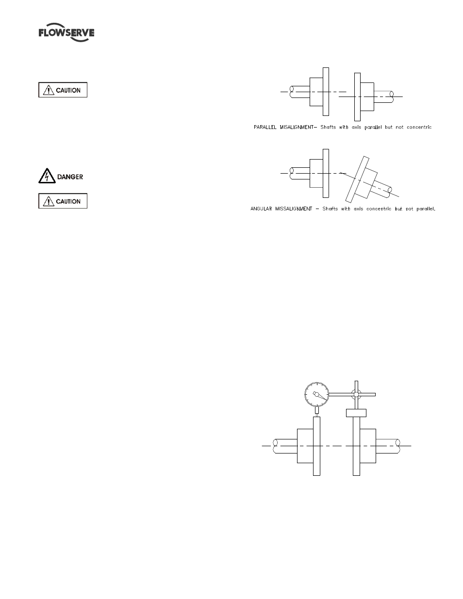
4.5.3.1 Parallel Alignment:
Checking parallel misalignment
Mount the magnetic base on the pump half coupling
hub, either the face or O.D. as shown in the sketch.
Place the dial indicator button on the outside diameter
of the driver half coupling hub.