Flowserve Type R User Manual
Page 38
R and RX SLURRY Pump USER INSTRUCTIONS ENGLISH
71569242 03-11 (E)
Page 38 of 56
flowserve.com
®
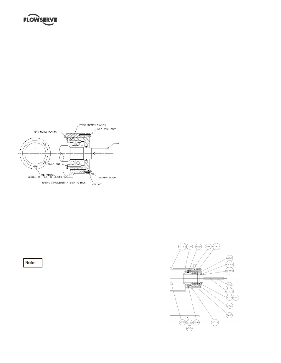
in step 6.10.2 . The bearings are mounted back to
back as shown.
c) Pack thrust bearing with grease if the bearings are
being grease lubricated.
d) Slide the bearing lockwashers [6541] on the shaft
and fit the bearing locknut [3712]. Tighten the
locknut snugly and allow to cool. Check the
tightness and bend one tab on the lockwasher into a
slot in the locknut. Protect the bearings from
contamination.
e) Carefully install the lip seal [4300] in the thrust
bearing housing [3230] by pressing it squarely into
the bore. The primary sealing lip [spring loaded] on
seal should be installed facing the bearing. A small
amount of sealant may be applied on the O.D. of the
seal prior to it’s installation.
f) Install the square head plug or grease fitting on the
tapped hole in the thrust bearing housing flange.
Lubricate the o-ring [4610] with the bearing lubricant
and assemble it into the groove of the outer
circumference of the thrust bearing housing [3230].
g) Lubricate the inside bore of the thrust bearing
housing [3230] and assemble it over the thrust
bearings. Care must be taken to prevent damage of
the seal on the shaft.
h) Using capscrews and lockwashers, attach the thrust
bearing clamp ring [2542] to the thrust bearing
housing [3230]. Lock the threads using Loctite 242
or equivalent.
The thrust bearing clamp ring [2542] is
provided with one extra hole midway between two
adjacent bolt holes to permit free oil flow. On oil
lubricated units, this hole must align with the cast oil
return at the bottom of the thrust bearing housing bore.
For grease lubricated units, this hole should be oriented
away from the cast oil return slot at the bottom the thrust
bearing housing bore.
Tighten the capscrews evenly ensuring that the clamp
ring is not distorted and gap to the bearing housing is
even all around. Tighten in accordance with Table 6.6.
6.10.3.2 Frame 4 pumps
a)
Place the thrust bearing clamp ring [2542] loosely
over the shaft on the largest diameter.
b)
Install the 4-point angular contact bearing [3031] on
the shaft [2110] using the same procedure as
described in step 6.10.2 and ensure it is seated
against the shoulder.
c)
Install the NU-roller bearing.
d)
Slide the bearing lockwashers [6541] on the shaft
and fit the bearing locknut [3712]. Tighten the
locknut snugly and allow to cool. Check the
tightness and bend one tab on the lockwasher into a
slot in the locknut. Protect the bearings from
contamination.
e)
Pack bearing with grease if the bearings are being
grease lubricated.
f)
Carefully install the lip seal [4300] in the thrust
bearing housing [3230] by pressing it squarely into
the bore. The primary sealing lip [spring loaded] on
seal should be installed facing the bearing. A small
amount of sealant may be applied on the O.D. of the
seal prior to its' installation.
g)
Install the square head plug or grease fitting on the
tapped hole in the thrust bearing housing flange.
Lubricate the o-ring [4610] with the bearing lubricant
and assemble it into the groove of the outer
circumference of the thrust bearing housing [3230].
h)
Lubricate the inside bore of the thrust bearing
housing [3230] and assemble it over the thrust
bearings. Care must be taken to prevent damage of
the seal on the shaft.
i)
Using capscrews and lockwashers, attach the thrust
bearing clamp ring [2542] to the thrust bearing
housing [3230]. Lock the threads using Loctite 242
or equivalent.
6.10.3.3 Frame 6
a) Place the shaft in a vertical position such that
the coupling end is up.
b) Lighting lubricate the shaft [2210] at the thrust
bearing position.