Flowserve Type R User Manual
Page 44
R and RX SLURRY Pump USER INSTRUCTIONS ENGLISH
71569242 03-11 (E)
Page 44 of 56
flowserve.com
®
Preparation for Operation.
e) It is recommended that the pump not be packed until
required. Refer to stuffing box packing procedure in
this section. Protect the stuffing box bore and seal
area with clean dry rags.
6.11 Impeller axial clearance adjustment
This procedure should not be used on units
with mechanical seals if the design is such that a
liquid seal cannot be maintained when the rotor is
moved axially against the liners.
A blind flange must be installed on the
suction to compress the liner nozzle as it will be in
service. If this is not done clearance could be lost
cause impeller to rub against the liner causing
damage to pump components.
NEVER ATTEMPT TO CHANGE THE
CLEARANCE WHEN THE PUMP IS RUNNING.
6.11.1 Frames 1-4
If the coupling has limited axial adjustment capability,
the pump and driver must be uncoupled prior to
adjusting the clearance in order to permit free
movement.
Install blind flange or pipe spool on
suction.
a) Loosen the two set screws retaining the deflector
[2540] and check that the deflector is free to move
axially on the shaft.
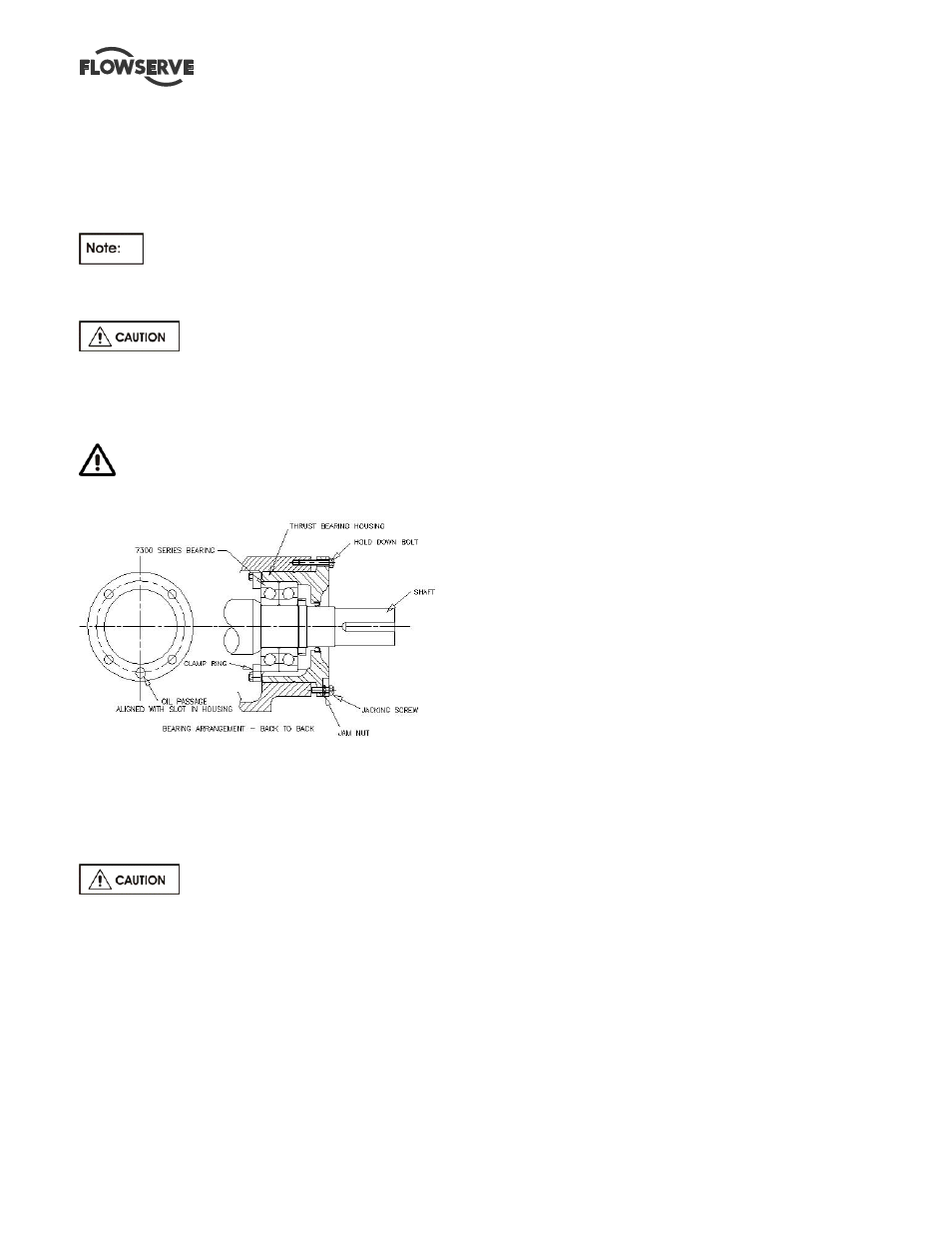
b) Loosen the thrust bearing housing jam nuts and
back off the three jacking screws at least 1.5 mm
(0.060 inch).
c) Move the rotor towards the suction side liner
[1916.1] by tightening the three hold-down
capscrews evenly and uniformly until the impeller
[2200] just touches the wear plate. This can be
best established by rotating the shaft and stopping
the forward motion at the first sign of rubbing. If
the shaft cannot be rotated, back off the bearing
housing with the jacking screws until a just
detectable rub is obtained. Check that the gap
between the two machined faces of the thrust
bearing housing [3230] and the bearing frame
[3130] are parallel within 0.076 mm (0.003 inch).
Adjust the jack screws and hold down capscrews
as required to achieve this parallelism. When the
impeller [2200] just touches the wear plate [1915]
and the thrust bearing housing [3230] is parallel to
the bearing frame [3130] the axial clearance
between the impeller and wear plate is zero.
6.11.1.1 Option1
a) Place a dial indicator, set to end of shaft [2110] or
on housing [3230] face.
b) Set indicator reading to zero (0).
c) Note required impeller clearance.
6.11.1.2 Option 2
a) Measure and record the axial gap between the
thrust bearing housing flange and bearing frame
end face. Determine the required impeller axial
running clearance from Section 3 and add this to
the above measurement to establish the required
gap setting.
6.11.1.3 Setting Axial Clearance
a) Loosen the thrust bearing housing hold down
capscrews slightly and tighten the jack screws.
Until the required dial indicator reading (6.11.1.1)
or housing gap reading (6.11.1.2) is achieved.
b) Alternately and gradually tighten the hold down
capscrews and jack screws until the required gap
setting is achieved at each hold down capscrew
location. Note that the gap at each jack screw will
be slightly larger as a result of minor elastic
distortion of the thrust bearing housing flange
caused by the high pre-load forces. The gap
setting at any set of screws must be the same
within 0.076 mm (0.003 in.). Careful attention to
this procedure will help ensure long thrust bearing
life.
c) While preventing the jack screws from rotating,
tighten the jam nuts to lock them in position.
d) Adjust the axial position of the deflector [2540] so
that it is clear of the line bearing cover [3260] by
approximately 0.75 mm (0.030 in.) and tighten the
setscrews firmly. Excessive tightening may mar
the shaft.
e) Manually rotate the shaft to ensure that there is no
rubbing or binding.
f) On belt driven units, adjust the pump or driver
sheave to maintain belt alignment. (Refer to
Section 4.5.2.2).
g) Check the alignment on direct driven units (refer