Flowserve Type R User Manual
Page 45
R and RX SLURRY Pump USER INSTRUCTIONS ENGLISH
71569242 03-11 (E)
Page 45 of 56
flowserve.com
®
to Section 4) and reassemble the coupling
components.
h) Replace any safety guards which may have been
removed.
6.11.2 Frame 0
If the coupling has limited axial adjustment capability,
the pump and driver must be uncoupled prior to
adjusting the clearance in order to permit free
movement.
Install blind flange or pipe spool on
suction.
a) Slide the rubber deflector [2540] away from the
face of the bearing frame.
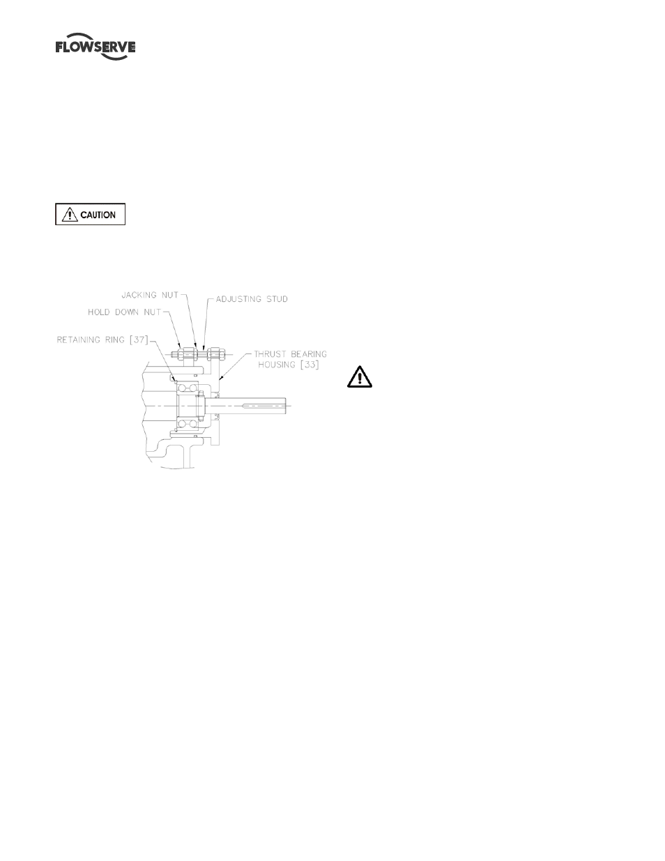
b) Loosen the thrust bearing housing Jacking Nut.
c) Move the rotor towards the suction side liner
[1916.1] by tightening the hold-down nut until the
impeller [2200] just touches the suction side liner
[1916.1]. This can be best established by rotating
the shaft and stopping the forward motion at the
first sign of rubbing. If the shaft cannot be rotated,
back off the bearing housing with the jacking
screws until a just detectable rub is obtained.
When the impeller [2200] just touches the suction
side liner [1916.1] the axial clearance between the
impeller and wear plate is zero.
6.11.2.1 Option1
d) Place a dial indicator, set to end of shaft [2110] or
on housing [3230] face.
e) Set indicator reading to zero (0).
f) Note required impeller clearance.
6.11.2.2 Option 2
b) Measure and record the axial gap between the
thrust bearing housing flange and bearing frame
end face. Determine the required impeller axial
running clearance from Section 3 and add this to
the above measurement to establish the required
gap setting.
6.11.2.3 Set Axial Clearance
d) Loosen the thrust bearing housing hold down nut
slightly and tighten the jacking nut. Until the
required dial indicator reading (6.11.2.1) or
housing gap reading (6.11.2.2) is achieved.
e) Tighten the hold down nut.
d) Adjust the axial position of the deflector [2540] so
that it is clear of the line bearing cover [3260] by
approximately 0.75 mm (0.030 in.)
e) Manually rotate the shaft to ensure that there is no
rubbing or binding.
f) On belt driven units, adjust the pump or driver
sheave to maintain belt alignment. (Refer to
Section 4.5.2.2).
g) Check the alignment on direct driven units (refer
to Section 4) and reassemble the coupling
components.
h) Replace any safety guards that may have been
removed.
6.11.3 Frame 6
NEVER ATTEMPT TO CHANGE THE
CLEARANCE WHEN THE PUMP IS RUNNING.
If the coupling has limited axial adjustment capability,
the pump and driver must be uncoupled prior to
adjusting the clearance in order to permit free
movement. Before doing so, ensure that the impeller
is free to rotate. Settled slurry will make impeller
adjustment difficult. The casing may have to be
flushed to remove heavy slurry.
a) Loosen the eight (8) cartridge hold down bolts
located on the side of the cartridge [3130].
b) Move the cartridge towards the pump suction by
adjusting the screw on the adjusting assembly
that is mounted on the pedestal between adjacent
ribs until the impeller makes contact with the
suction side liner [1916.1]. It is advisable to rotate
shaft/impeller while making the adjustment as the
first sign of contact will signify zero clearance. If
the impeller can not be rotated the cartridge
should be adjusted backwards until the impeller is
just making contact. Place a dial indicator on to
the shaft end or bearing cartridge and set
indicator to zero.
c) Determine the required impeller axial running
clearance from Section 3 and add this to the
above measurement to establish the required gap
setting. Adjust the cartridge/shaft away from the
casing until the desired reading is achieved.
d) Tighten the hold down bolts on the cartridge side
flanges in accordance with tables in 6.6.