Flowserve Type R User Manual
Page 23
R and RX SLURRY Pump USER INSTRUCTIONS ENGLISH
71569242 03-11 (E)
Page 23 of 56
flowserve.com
®
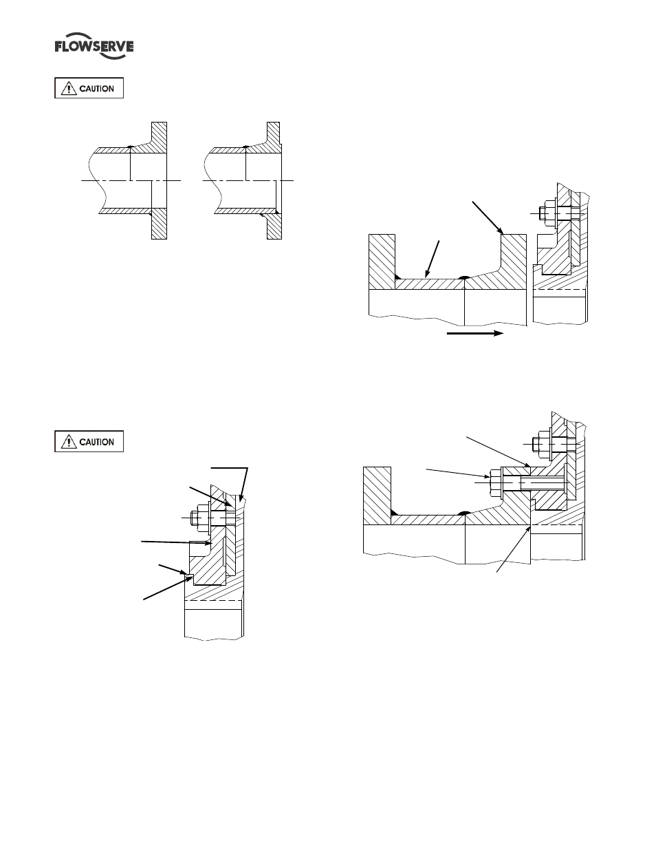
Do not use raised face flanges
RECOMMENDED
DO NOT USE
WELD NECK
-NO RAISED FACE
EQUIVALENT TO
WELD NECK FLANGE
WELD NECK
-RAISED FACE
SLIP-ON FLANGE
4.7.1.2 Flange Size
It is necessary that the I.D. of the pipe flange match
the I.D. of the properly seated liner nozzle. The
suction flange face must be to the nominal flange
size, ie for a 12” flange the flange ID should be 12”.
This can be a particular problem where thinner
walled piping is used which has larger inside
diameters. Weld neck flanges that match the thinner
pipes will reduce clamping area at pump flange and
could lead to a collapse of the suction nozzle in the
pump.
Flange I.D. to be nominal size.
Liner
Liner support plate
Casing
Rubber seal lip extension
Recess
4.7.1.3 Flange Design
Depicted in the sketch above is the suction of the
pump but information applies to the discharge as
well. The rubber seal lip, which protrudes beyond the
flange face of the metal casing must be completely
compressed at assembly to ensure a seal and retain
the liner nozzle. At assembly and prior to installing
piping ensure that the lip is properly seated in the
recess of the casing.
4.7.1.4 Spool Installation
The sketch below illustrates that a short spool is
recommended to connect to the flange. The spool
should be moved perpendicular to the flange so that
the rubber sealing lip is not dislodged. If the spool is
slid into the flange from the side the sealing lip may
be pushed out of the recess and/or the rubber nozzle
distorted making it impossible to obtain a seal.
Movement
Flat faced flange
Short Spool Piece
The spool piece when bolted to the casing will fully
compress the rubber sealing lip into the recess, this
will provide a positive metal to metal fit. When the
spool is used with a properly designed flange the
Check for uniformity
Bolt
Metal to Metal Fit
compression of the rubber is controlled. The flange
bolts are designed for a maximum engagement of
1.5X the bolt size. Use of longer bolts in the suction
could distort and damage the liner. Bolts that are too
long in the discharge may bottom out in the blind
flange. Before the bolts are tightened ensure that the
I.D. of the spool is even and uniform with the rubber
bore. Figure 8C shows the alignment and illustrates
the suction flange bolting.