Grouting, Initial alignment, Grouting (4.4) – Flowserve Durco Mark 3 ISO Frame Mounted User Manual
Page 14: Thermal expansion (4.5.1)
DURCO MARK 3 ISO FRAME MOUNTED ENGLISH 85392719 12-14
Page 14 of 52
flowserve.com
d)
The pump and driver have been aligned before
dispatch however the alignment of pump and motor
half coupling must be checked. If this is incorrect, it
indicates that the baseplate has become twisted
and should be corrected by re-shimming.
e)
If not supplied, guarding shall be fitted as necessary
to meet the requirements of ISO 12100 and EN953.
4.4
Grouting
Where applicable, grout in the foundation bolts.
After adding pipework connections and rechecking the
coupling alignment, the baseplate should then be
grouted in accordance with good engineering practice.
Fabricated steel, folded steel and cast iron baseplates
can be filled with grout. Polycrete baseplates cannot be
grouted in the same way, see their User Instructions
71569284 (E) for installation and use. If in any doubt,
please contact your nearest service center for advice.
Grouting provides solid contact between the pump unit
and foundation, prevents lateral movement of vibrating
equipment and dampens resonant vibrations.
Foundation bolts should only be fully tightened when
the grout has cured.
4.5
Initial alignment
4.5.1
Thermal expansion
The pump and motor will normally have
to be aligned at ambient temperature with an allowance
for thermal expansion at operating temperature. In
pump installations involving high liquid temperatures,
typically above 100 ºC (212 ºF), the unit should be run
at the actual operating temperature, shut down and the
alignment checked immediately.
4.5.2
Alignment methods
Pump and driver must be isolated
electrically and the half couplings disconnected
.
The alignment MUST be checked.
Although the pump will have been aligned at the
factory it is most likely that this alignment will have
been disturbed during transportation or handling. If
necessary, align the motor to the pump, not the pump
to the motor.
Alignment is achieved by adding or removing shims
under the motor feet and also moving the motor
horizontally as required. In some cases where the
alignment cannot be achieved it will be necessary to
move the pump before recommencing the above
procedure.
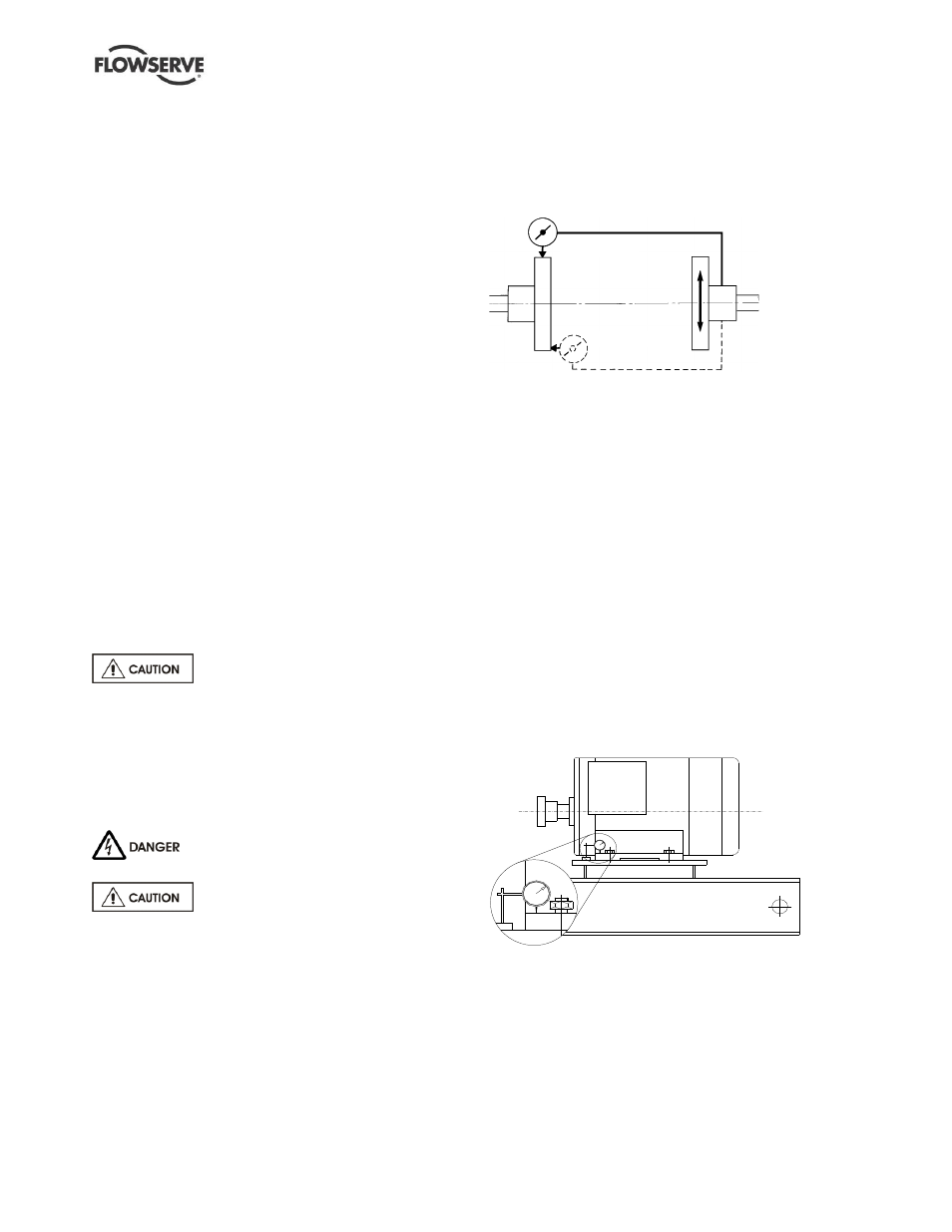
For couplings with narrow flanges use a dial indicator
as shown. The alignment values are maximums for
continuous service.
P a r a l l e l
A n g u l a r
Permissible misalignment limits at working temperature:
Parallel alignment
-
0.25 mm (0.010 in.) TIR maximum
Angular alignment
- 0.3 mm (0.012 in.) TIR maximum for couplings
not exceeding 100 mm (4 in.) flange diameter
- 0.5 mm (0.020 in.) TIR maximum for couplings
over 100 mm (4 in.) diameter
When checking parallel alignment, the total indicator
read-out (TIR) shown is twice the value of the actual
shaft displacement.
Align in the vertical plane first, then horizontally by
moving motor. Maximum pump reliability is obtained
by near perfect alignment of 0.05 - 0.075 mm (0.002 -
0.003 in.) parallel and 0.05 mm (0.002 in.) per 100 mm
(4 in.) of coupling flange diameter as angular
misalignment.
4.5.3
Check for soft foot
This is a check to ensure that there is no undue stress
on the driver holding down bolts; due to non-level
baseplate or twisting. To check, remove all shims and
clean surfaces and tighten down driver to the baseplate.
Set a dial indicator as shown in sketch and loosen off
the holding down bolt while noting any deflection
reading on the dial test Indicator - a maximum of
0.05 mm (0.002 in.) is considered acceptable but any
more will have to be corrected by adding shims.