Sealing arrangements, Sealing arrangements (6.11), 11 sealing arrangements – Flowserve Durco Mark 3 ISO Frame Mounted User Manual
Page 33
DURCO MARK 3 ISO FRAME MOUNTED ENGLISH 85392719 12-14
Page 33 of 52
flowserve.com
Impeller assembly with key drive impeller
6.10.4.2
a)
Fit a new impeller sealing gasket [4590.4] against
shaft shoulder.
b)
Fit impeller key [6700.2].
c)
Assemble impeller [2200] onto the shaft [2100].
d)
Fit a new O-ring [4610.5] into the impeller nut
[2912.1/2912.2] groove.
e)
Apply anti-galling compound (which does not
contain copper) to the impeller nut threads to help
any subsequent removal.
f)
Fit impeller nut [2912.1/2] onto the shaft [2100] and
torque up.
6.10.5
Assembly of power-end into casing
a)
Fit a new gasket [4590] into the casing [1100].
On the recessed impeller a new gasket is
required each side of the distance ring [2510.2].
b)
Ensure bearing housing and adaptor concentricity
and squareness.
c)
Install the power-end assembly into the pump
casing. Coat the studs [6572.1] with anti-galling
compound and tighten nuts [6580.1] onto casing.
d)
Check impeller clearance against original setting or
process requirement and adjust as necessary. (See
section 6.7, Setting impeller clearance.)
e)
Ensure that all other items have been re-attached
and all fasteners tightened to the correct torques,
then follow the instructions in the sections on
Installation and Commissioning.
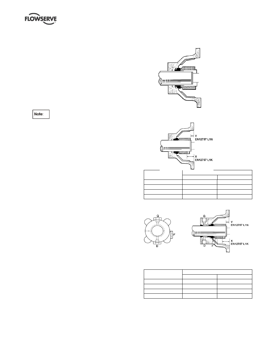
6.11 Sealing arrangements
The following section shows details of the seal
arrangements. The dimensions provided are for non-step
balanced mechanical seals conforming to EN 12757 L1K
and L1N. Contact your nearest Flowserve sales office or
service center if you require further information, such as a
mechanical seal dimensional drawing, or are unsure of the
specific arrangement supplied. Refer also to section
4.6.5, Auxiliary piping.
6.11.1
Single seal types
Single stepped balanced seal
6.11.1.1
Single unbalanced (or inherently balanced)
6.11.1.2
seal
Bearing housing
Setting dimension mm (in.)
X
Y
Frame 1
23.5 (0.925)
11.0 (0.433)
Frame 2
34.0 (1.339)
19.0 (0.748)
Frame 3
33.5 (1.319)
11.0 (0.433)
Frame 4
51.5 (2.028)
24.0 (0.945)
Single seal with external neck bush
6.11.1.3
Q - Rp ¼ in. quench
D - Rp ¼ in. drain
F - Rp ¼ in. flush
Bearing housing
Setting dimension mm (in.)
X
Y
Frame 1
23.5 (0.925)
11.0 (0.433)
Frame 2
34.0 (1.339)
19.0 (0.748)
Frame 3
33.5 (1.319)
11.0 (0.433)
Frame 4
51.5 (2.028)
24.0 (0.945)