Flowserve Durco Mark 3 ISO Frame Mounted User Manual
Page 32
DURCO MARK 3 ISO FRAME MOUNTED ENGLISH 85392719 12-14
Page 32 of 52
flowserve.com
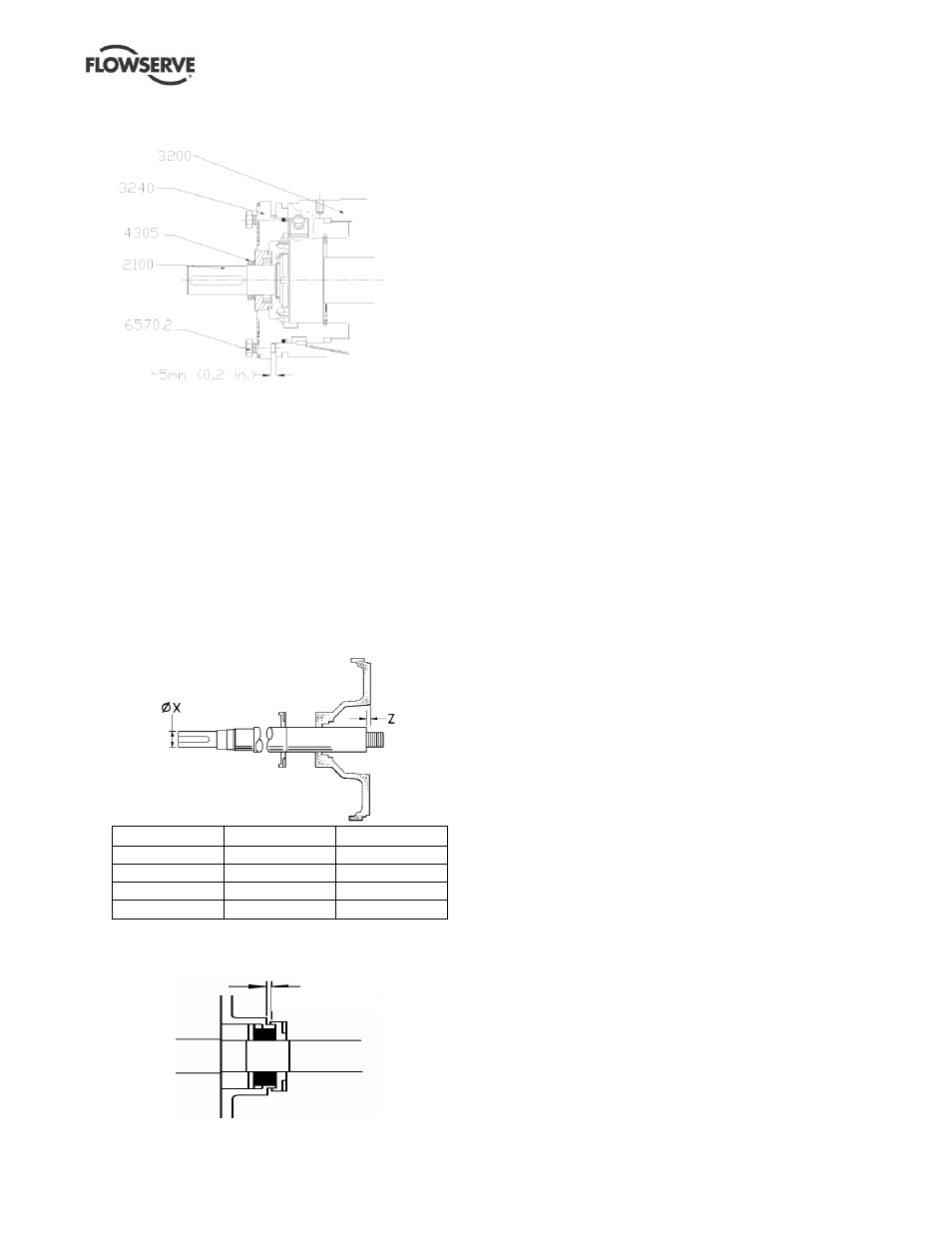
o) Install the shaft assembly into the bearing housing
[3200] until the gap is approximately 5 mm (0.2 in.).
Fit the bearing carrier screws [6570.1] but do not
tighten.
p)
Press drive side v-ring [4305] and pump side liquid
deflector [2540] onto shaft [2100] where applicable.
The V-ring type shall be fitted with light contact with
the bearing carrier [3240].
q)
The pump side deflector [2540] (this feature is
integral with some proprietary labyrinth seals)
should only be set in its final position after setting
the shaft axial position.
r)
Temporarily fit the cover [1220] to the power-end.
The cover, above 125 size, is retained by studs
[6580] and their nuts. The shaft [2100] may now be
positioned in relation to the cover face, by rotating
the carrier, position as shown below:
Bearing housing
Dia. X mm (in.)
Z mm (in.)
Frame 1
24 (0.945)
9 (0.354)
Frame 2
32 (1.260)
17 (0.669)
Frame 3
42 (1.654)
9 (0.354)
Frame 4
48 (1.890)
22 (0.866)
t) The pump side deflector [2540] may then be moved
towards the bearing housing [3200] and set with its
clearance.
0. 5 to 2 mm
(0. 02 to 0. 08 i n. )
6.10.2
Seal cover and seal assembly
a)
Extreme cleanliness is required. The sealing faces
and shaft [2100] or sleeve [2400] surface must be
free from scratches or other damage.
b)
Refer to section 6.11, Seal arrangements, for seal
diagrams.
c)
Carefully press the stationary seat into the cover
[1220] or mechanical seal cover [4213], ensuring
that the seating ring is not deformed. Where an
anti-rotation pin is fitted ensure that correct
engagement with the slot is achieved.
d) Place any separate seal covers over the shaft [2100].
e)
Refer to manufacturer's instructions to position the
mechanical seal rotating elements. Tighten any
drive screws in the seal drive collar. For precise
compression most cartridge seals should be set
after complete pump assembly.
f)
Fit the cover [1220] into the bearing housing [3200]
and tighten all fasteners.
6.10.3
Gland packed stuffing box assembly
a)
Assemble the gland packing [4130] into the cover
before fitting on to the shaft [2100], see 6.11.6.
b)
Stagger the joints in the gland packing by 90
degrees to each other.
c)
The lantern ring halves [4134], if required, should be
positioned mid-way along the packing.
d)
Position the gland [4120] squarely against the last
ring and tighten the gland nuts finger-tight only.
Install into bearing housing assembly, fit the two
studs and nuts to hold the cover [1220] in place.
e)
Check that the shaft [2100] rotates freely.
6.10.4
Impeller assembly and setting
Impeller assembly and setting - screwed
6.10.4.1
on impeller/locking screw
a) Fit a new O-ring [4610.1] into the impeller [2200]
using a small amount of grease to hold it in place.
Apply anti-galling compound (which does not
contain copper) to the impeller thread to help
subsequent removal.
b)
Assemble impeller [2200] onto the shaft [2100].
c) Tighten the impeller. Use the same method as in
disassembly but rotating in opposite direction. A
few sharp strikes will tighten it to the correct level.
d) Fit a new O-ring [4610.6] into the locking screw
[6570.6] using a small amount of grease to hold it in
place. Apply anti-galling compound (which does
not contain copper) to the impeller thread to help
subsequent removal (applicable only on the locking
screw
configuration).
e)
Tighten the locking screw (left hand thread) to the
predefined torque. Refer to section 6.6 (applicable
only on the locking screw configuration)