Disassembly, Disassembly (6.8), Dismantling (6.8, disassembly) – Flowserve Durco Mark 3 ISO Frame Mounted User Manual
Page 29
DURCO MARK 3 ISO FRAME MOUNTED ENGLISH 85392719 12-14
Page 29 of 52
flowserve.com
b) Turn the bearing carrier [3240] counter-clockwise
until the impeller [2200] comes into light contact
with the rear cover [1220]. Rotating the shaft
[2100] at the same time will accurately determine
when a detectable rub is obtained. This is the zero
clearance setting.
c) Rotating the bearing carrier [3240] the width of one of
the indicator patterns cast into the bearing carrier
moves the impeller [2200] axially 0.1 mm (0.004 in.).
Example: for an impeller setting of 0.4 mm (0.016 in.)
simply move the bearing carrier clockwise four indicator
patterns for the required clearance.
d) Use the indicator pattern closest to the top center of
the bearing housing as the reference point to begin
adjustment.
e) After obtaining the proper clearance, listed in the table
above, tighten the set-screws [6570.1] evenly to lock
the impeller [2200] and shaft [2100] assembly.
Tightening the screws [6570.1] will cause the impeller
to move 0.05 mm (0.002 in.) closer to the rear cover
because of the internal clearance in the bearing
carrier threads. This must be considered when setting
the impeller clearance.
f) If a cartridge seal [4200] is fitted it should be reset
at this point.
g) Check that the shaft can turn freely without binding.
h) Ensure the coupling distance between shaft ends
(DBSE) is correct. Reset/re-align if necessary.
6.7.3
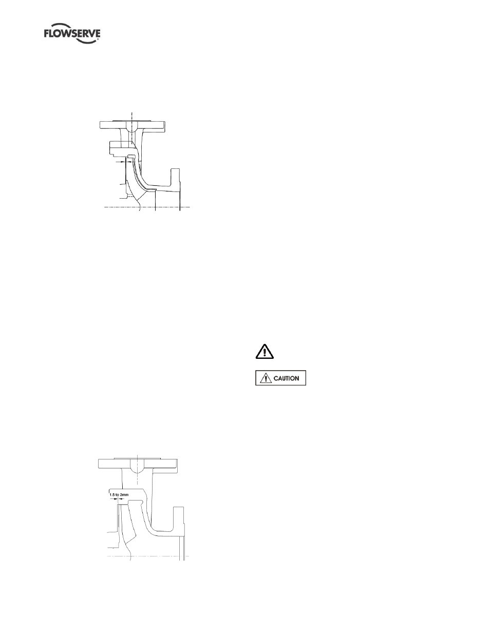
Setting recessed impeller rear clearance
a) Recessed open impellers are set off the cover. This
allows the impeller to be set without the casing.
b) Turn the bearing carrier [3240] counter-clockwise
until the impeller [2200] comes into light contact
with the cover [1220]. Rotating the shaft [2100] at
the same time will accurately determine when a
detectable rub is obtained. This is the zero
clearance setting.
c) Rotating the bearing carrier [3240] the width of one of
the indicator patterns cast into the bearing carrier
moves the impeller [2200] axially 0.1 mm (0.004 in.).
Example: for an impeller setting of 1.5 mm (0.059 in.)
simply move the bearing carrier clockwise fifteen
indicator patterns for the required clearance.
d) Use the indicator pattern closest to the top center of
the bearing housing as the reference point to begin
adjustment.
e) After obtaining the proper clearance of 1.5 mm
(0.059 in.) to 2 mm (0.079 in.), tighten the set-
screws [6570.1/2] evenly to lock the impeller [2200]
and shaft [2100] assembly.
Tightening the screws
will cause the impeller to move 0.05 mm (0.002 in.)
closer to the rear cover because of the internal
looseness in the bearing carrier threads. This must
be considered when setting the impeller clearance.
If possible, check results with a feeler gauge.
f) If a cartridge seal [4200] is fitted it should be reset
at this point.
g) Check that the shaft can turn freely without binding.
h) Ensure the coupling distance between shaft ends
(DBSE) is correct. Reset/re-align if necessary.
6.8
Disassembly
Refer to Safety section before dismantling the
pump.
Before dismantling the pump for
overhaul, ensure genuine Flowserve replacement parts
are available.
Refer to sectional drawings for part numbers and
identification. (See section 8, Parts lists and drawings.)
6.8.1
Bearing housing disassembly
To remove, proceed as follows:
a)
Disconnect all auxiliary pipes and tubes where
applicable.
b)
Remove coupling guard and disconnect coupling.
c) If oil lubricated frame, drain oil by removing drain plug.
d)
Record the gap between the bearing carrier [3240]
and bearing housing [3200] so that this setting can
be used during workshop assembly.
e)
Place hoist sling through bearing housing adaptor
window.
f)
Remove casing nuts [6582.1] and support foot
[3134] to baseplate screws.