Electrical connections, Electrical connections (0) – Flowserve Durco Mark 3 ISO Frame Mounted User Manual
Page 19
DURCO MARK 3 ISO FRAME MOUNTED ENGLISH 85392719 12-14
Page 19 of 52
flowserve.com
4.6.5
Final checks
Check the tightness of all bolts in the suction and
discharge pipework. Check also the tightness of all
foundation bolts.
4.6.6
Auxiliary piping
The connections that are to be piped up
will have been fitted with protective metal or plastic
plugs which will need to be removed.
Pumps fitted with packed glands
4.6.6.1
When suction pressure is below ambient pressure and
differential head is less than 10 m (32.8 ft), it may be
necessary to feed gland packing with liquid to provide
lubrication and prevent the ingress of air.
Pumps fitted with mechanical seals
4.6.6.2
The Seal Sentry design of the anti-vortex chamber for
single internal seals provides excellent liquid circulation
around the seal and will not normally require a separate
flush.
Single seals requiring re-circulation will normally be
provided with the auxiliary piping from pump casing
already fitted.
Flowserve seal connections are designated as follows:
Q
-
quench
F
-
flush
D
-
drain outlet
BI
-
barrier fluid in (double seals)
BO - barrier fluid out (double seals)
H
-
heating jacket
C
-
cooling jacket
Seal chambers/covers having an auxiliary quench
connection, require connection to a suitable source of
liquid flow, low pressure steam or static pressure from a
header tank. Recommended pressure is 0.35 bar
(5 psi) or less. Check General arrangement drawing.
Double seals require a barrier liquid between the seals,
compatible with the pumped liquid.
With back-to-back double seals, the barrier liquid
should be at a minimum pressure of 1 bar (14.5 psi)
above the maximum pressure on the pump side of the
inner seal (see appropriate chart). The barrier liquid
pressure must not exceed limitations of the seal on the
atmospheric side. For toxic service the barrier liquid
supply and discharge must be handled safely and in
line with local legislation
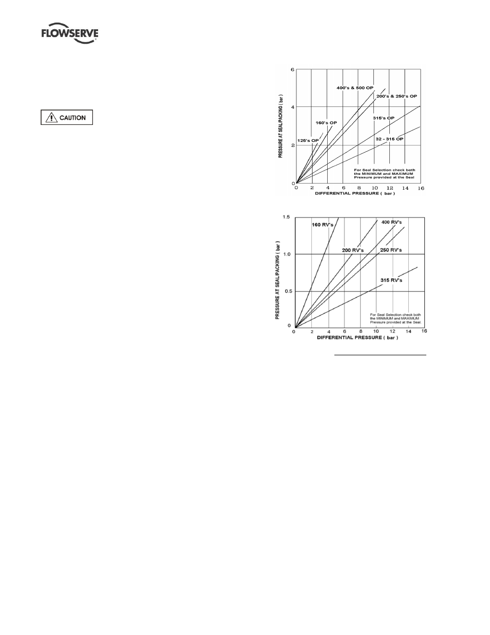
It is important to understand the pressure at the rear of
the impeller and in the seal chamber, to have reliable
seals. Consult Flowserve or the seal manufacturer for
guidance if required.
Open impellers (OP) generated rear pressure:
Reverse vane impellers (RV) generated rear pressure:
Notes:
Differential pressure in bar = Head in meters x specific gravity
10.19
a)
Total seal pressure is equal to the sum of pressure at seal (from
the applicable chart above) plus suction pressure.
b) Ensure to check the seal minimum and maximum pressure limits
are not exceeded.
Special seals may require modification to auxiliary
piping described above. Consult Flowserve if unsure of
correct method or arrangement. For pumping hot
liquids, to avoid seal damage, it is recommended that
any external flush/cooling supply be continued after
stopping the pump. Dual seals require a barrier liquid
between the seals compatible with the pumped liquid.
Pumps fitted with heating/cooling jackets
4.6.6.3
Connect the heating/cooling pipes from the site supply.
The top connection should be used as the outlet to
ensure complete filling/venting of the annulus with
heating/cooling liquids; steam is usually in at the top,
out at the bottom.