Spare parts, Recommended spares, Tools required – Flowserve Durco Mark 3 ISO Frame Mounted User Manual
Page 27: Ordering spare parts (6.3.1), Recommended spares (6.4), Replacement parts (6.3 and 6.4), Spare parts (6.3), Storage, spare parts (6.3.2), Tools required (6.5), 3 spare parts
DURCO MARK 3 ISO FRAME MOUNTED ENGLISH 85392719 12-14
Page 27 of 52
flowserve.com
The bearing temperature may be allowed to rise to
50 ºC (90 ºF) above ambient, but should not exceed
82 ºC (180 ºF) (API 610 limit). A continuously rising
temperature, or an abrupt rise, indicate a fault.
Pumps that handle high temperature liquids may
require their bearings to be cooled to prevent bearing
temperatures exceeding their limits.
Grease lubricated bearings
6.2.3.2
When grease nipples are fitted, one charge between
grease changes is advisable for most operating
conditions; ie 2 000 hours interval. Normal intervals
between grease changes are 4 000 hours.
For food grade grease the grease change and
relubrication intervals are half those of conventional
greases.
The characteristics of the installation and severity of
service will determine the frequency of lubrication.
Lubricant and bearing temperature analysis can be useful
in optimizing lubricant change intervals.
The bearing temperature may be allowed to rise to
55 ºC (99 ºF) above ambient, but should not exceed
95 ºC (204 ºF).
Never mix greases containing different
bases, thickeners or additives.
6.2.4
Mechanical seals
When leakage becomes unacceptable the seal [4200]
will need replacement.
6.2.5
Gland packing
The stuffing box split gland can be completely removed for
re-packing or to enable the addition of extra rings of
packing. The stuffing box is normally supplied with a
lantern ring to enable a clean or pressurized flush to the
center of the packing. If not required, this can be replaced
by an extra 2 rings of packing.
6.3
Spare parts
6.3.1
Ordering of spares
Flowserve keeps records of all pumps that have been
supplied. When ordering spares the following
information should be quoted.
1)
Pump serial number.
2)
Pump size.
3)
Part name – taken from section 8.
4)
Part number – taken from section 8.
5)
Number of parts required.
(The pump size and serial number are shown on the
pump nameplate.)
To ensure continued satisfactory operation, replacement
parts to the original design specification should be obtained
from Flowserve. Any change to the original design
specification (modification or use of a non-standard part) will
invalidate the pump safety certification.
6.3.2
Storage of spares
Spares should be stored in a clean dry area away from
vibration. Inspection and re-treatment of metallic
surfaces (if necessary) with preservative is
recommended at 6 monthly intervals.
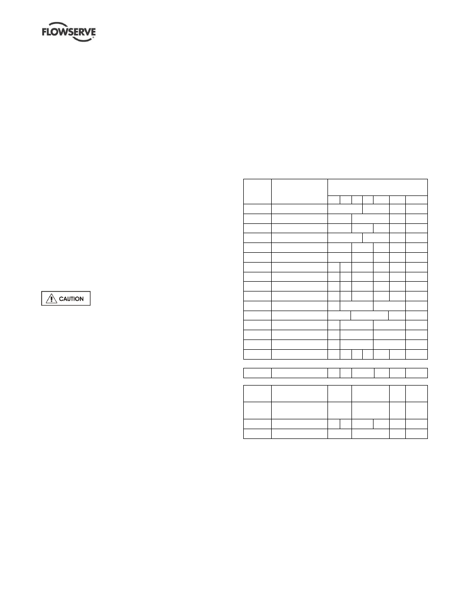
6.4
Recommended spares
For two years operation (as per VDMA 24296).
Part
no.
Designation
Number of pumps
(including stand-by)
2 3 4 5 6/7 8/9 10(+)
2200
Impeller
1
2
3
30%
2100
Shaft
1
2
3
30%
3712.1 Bearing locknut
1
2
3
4
50%
2400
Sleeve (if fitted)
2
3
4
50%
3011
Radial ball bearing
1
2
3
4
50%
3013
Thrust bearing
1
2
3
4
50%
4590.1 * Gasket
4 6
8
9
12 150%
4610.1 O-ring
4 6
8
9
12 150%
4610.2 O-ring
4 6
8
9
10 100%
4610.6 O-ring
4 6
8
9
10 100%
2540
Deflector
1
2
3
30%
4130
Gland packing
2
3
4
40%
4134
Lantern ring
1
2
3
30%
4200
Mechanical seals
1
2
3
30%
4305
V-ring
1
2
3
30%
-
Power end
-
-
-
-
-
1
2
* Note: for recessed impeller version replace with the following part:
4590.1 Gasket
8 12
16
18
24 300%
Additional spares for keyed impeller option
2912.1 /
2912.2
Impeller nut
1
2
3
30%
4610.4
O-ring
(if sleeve fitted)
2
3
4
50%
4610.5 O-ring
4 6
8
9
12 150%
6700.2 Key
1
2
3
30%
6.5
Tools required
A typical range of tools that will be required to maintain
these pumps is listed below.
Readily available in standard tool kits, and dependent
on pump size:
Open ended spanners (wrenches) to suit up to
M 48 screws/nuts
Socket spanners (wrenches), up to M 48 screws
Allen keys, up to 10 mm (A/F)
Range of screwdrivers
Soft mallet