Storage, Recycling and end of product life, Description – Flowserve IDP CPXV User Manual
Page 11: Configurations, Name nomenclature, Design of major parts, Configurations (3.1), Name nomenclature (3.2), Storage, pump (2.4)
CPXV and CPXRV USER INSTRUCTIONS ENGLISH 71569193 09-14
Page 11 of 48
flowserve.com
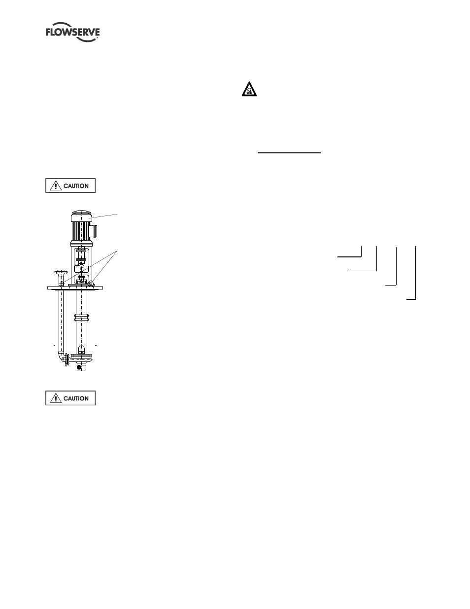
Slings, ropes and other lifting gear must be
positioned where they cannot slip and where a
balanced lift is obtained.
Most units are supplied with four lifting points on the
pump sole plate [6140]. Attach D links onto all four
lifting points. Lift the pump up to the vertical,
suspending initially from only two of the D links on the
sole plate while the pump casing foot remains resting on
the floor, until almost vertical. Then use all four lifting
points to lift completely off the floor.
For improved stability unbolt the driver and lift the
driver and pump separately.
To avoid distortion, the pump unit
should be lifted as shown.
2.4 Storage
Store the pump in a clean, dry location
away from vibration. Leave piping connection covers in
place to keep dirt and other foreign material out of pump
casing. Turn pump at intervals to prevent brinelling of
the bearings and the seal faces, if fitted, from sticking.
The pump may be stored as above for up to six
months. Consult Flowserve for preservative actions
when a longer storage period is needed.
2.5 Recycling and end of product life
At the end of the service life of the product or its
parts, the relevant materials and parts should be
recycled or disposed of using an environmentally
acceptable method and local requirements. If the
product contains substances that are harmful to the
environment, these should be removed and disposed
of in accordance with current regulations. This also
includes the liquids and or gases that may be used in
the "seal system" or other utilities.
Make sure that hazardous substances are
disposed of safely and that the correct personal
protective equipment is used. The safety
specifications must be in accordance with the current
regulations at all times.
3
DESCRIPTION
3.1 Configurations
The pump is a modular designed centrifugal pump
that can be built to achieve almost all chemical liquid
pumping requirements. (See 3.2 and 3.3 below.)
3.2 Name nomenclature
The pump size will be engraved on the nameplate
typically as below:
80-50CPXV200
Nominal suction size in mm
Nominal discharge size in mm
Configuration
Nominal ISO maximum impeller diameter in mm
The typical nomenclature above is the general guide to
the CPXV configuration description. Identify the actual
pump size and serial number from the pump nameplate.
Check that this agrees with the applicable certification
provided
.
3.3 Design of major parts
3.3.1
Pump casing
The pump casing is designed for operation when
submerged in the sump liquid.
3.3.2
Impeller
An open impeller is fitted. (On the CPXRV the impeller
is recessed within the back of the casing and the
impeller setting is to the rear backvanes.)
3.3.3
Shaft
The shaft has a keyed drive coupling. It is supported by
rolling bearing(s) above the sole plate and journal
bearing(s) below.
3.3.4
Bearing housing
The bearing housing enables adjustment of impeller
face clearance on the open impeller via the bearing
carrier jacking screws.
For lifting the driver refer to the
dimension drawing of the driver
Lift points for the pump or the
pump and the driver