Flowserve IDP CPXV User Manual
Page 31
CPXV and CPXRV USER INSTRUCTIONS ENGLISH 71569193 09-14
Page 31 of 48
flowserve.com
into the motor stool and sole plate until the gap
(above), is approximately 4 mm (0.16 in.).
c)
Install the bearing carrier hexagon screws
[6570.3] and the hexagon screws [6570.4] and
hexagon nuts [6580.1], but do not tighten.
d) Press the flinger [2540.2] onto the shaft, where
applicable. This should be set between 0.5 and
2 mm (0.02 and 0.08 in.) from the bearing carrier.
e)
Turn the shaft [2100] to check for freedom from
rubbing.
f)
Refit the coupling [7000].
6.11.5 Impeller and casing assembly
6.11.5.1 Impeller assembly with threaded on
impeller
a)
Fit a new O-ring [4610.1] into the impeller using a
small amount of grease to hold it in place. Apply
anti-galling compound (which does not contain
copper) to the impeller thread to help subsequent
removal.
b)
Assemble impeller [2200] onto the shaft [2100].
c) Tighten the impeller. Use the same method as in
disassembly but rotate in opposite direction. A
few sharp strikes will tighten it to the correct level.
d)
Clean the casing spigot and gasket position
mating surfaces.
e)
Fit a new casing gasket [4590.1].
f)
Install the pump casing with a new casing to
discharge gasket [4590.2].
g)
Install casing hexagon screws [6570.2] to the
specified torques.
h)
Check impeller front clearance against original
setting, or process requirement, and adjust as
necessary. (See section 6.7, Setting impeller
clearance.)
i)
Check freedom to rotate within pump casing.
6.11.5.2 Impeller assembly with key drive impeller
a)
Fit a new impeller sealing gasket [4590.4] against
shaft shoulder.
b)
Fit impeller key [6700.2].
c)
Assemble impeller [2200] onto the shaft [2100].
d) Fit a new O-ring [4610.5] into the impeller locking
nut groove.
e)
Apply anti-galling compound (which does not
contain copper) to the impeller nut threads to
help any subsequent removal.
f)
Fit impeller nut [2912] onto the shaft and torque up.
g)
Clean the casing spigot and gasket position
mating surfaces.
h)
Fit a new casing gasket [4950.1].
i)
Install the pump casing with a new casing to
discharge gasket [4950.2].
j)
Install casing hexagon screws [6570.2] to the
specified torques.
k)
Check impeller front clearance against original
setting, or process requirement and adjust as
necessary. (See section 6.7, Setting impeller
clearance.)
l)
Check freedom to rotate within pump casing.
6.11.6 Cartridge seal assembly (if fitted)
a)
To set, or reset, a cartridge seal having a PTFE
setting ring-throttle and no separate setting clips,
finger tighten the seal cover stud nuts, then fully
torque up the sleeve screws.
b)
Torque up the seal cover stud nuts.
6.11.7 Coupling, motor and ancillaries
a) Reconnect pump ancillary fittings and piping.
b)
Install pump into sump and connect up remaining
fittings and piping.
c)
Re-check freedom of shaft to rotate by hand.
d)
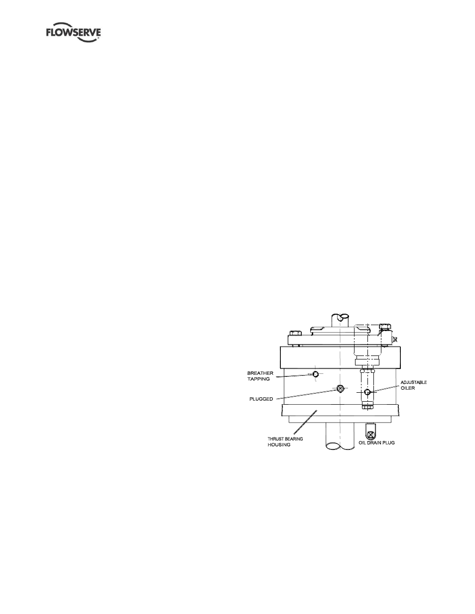
If pump has an oil lubricated thrust bearing, ensure
the oil breather and oiler are assembled in their
correct tappings as shown below and fill with the
correct grade and quantity of oil through the oiler.
e)
Re-install motor (check for correct rotation) and
then fit coupling drive element and guards.
f)
If all is correct continue with the procedure described
under Section 4, Installation, and section 5,
Commissioning, start-up, operation and shutdown.