Stopping and shutdown, Stop/start frequency (5.8.8), 9 stopping and shutdown – Flowserve IDP CPXV User Manual
Page 22
CPXV and CPXRV USER INSTRUCTIONS ENGLISH 71569193 09-14
Page 22 of 48
flowserve.com
Set the alarm at (t+tb-ta+5) º
C (t+tb-ta+10 ºF)
and the trip at 100 ºC (212 ºF) for oil lubrication
and 105 ºC (220 ºF) for grease lubrication.
Ensure that the ATEX temperature class limit is
not exceeded if the pump is operating in a
hazardous area. The normal bearing
temperature T
n
is = t+t
b
-t
a
where T
n
<T
c
. In the
case of T5 and T6, the critical bearing
temperature T
c
= 65
o
C (T6) or 80
o
C (T5)
It is important, particularly with grease lubrication, to
keep a check on bearing temperatures. After start-up
the temperature rise should be gradual, reaching a
maximum after approximately 1.5 to 2 hours. This
temperature rise should then remain constant or
marginally reduce with time. (Refer to section 5.2.5
for further information.)
5.8.4
Line bearing temperature
When pump are equipped for
monitoring of line bearing temperature the normal
and shut off levels must be set to:
The normal bearing temperature T
n
is the flush
line maximum liquid temperature +5 °C (+9 °F)
The critical bearing temperature T
c
is set to
applicable ATEX class limit -10 °C (-18 °F).
(See table in section 1.6.4.3.)
If the measured bearing temperature exceeds the T
c
value the system must give an alarm to the pump
operator or the pump must be automatically stopped
and the cause investigated before restarting the pump.
5.8.5
Line bearing lubrication
For pumps equipped with flow
monitor for the individual line bearings, the bearing
flush to each line bearing shall be controlled
according the following table:
Pump frame size
Normal flow Q
n
l/min (USgpm)
Critical flow Q
c
l/min (USgpm
1
4.2 (1.2)
3.6 (1)
2
5 (1.4)
4.3 (1.2)
3
5.9 (1.6)
5 (1.4)
4
6.7 (1.8)
5.7 (1.5)
For bearing frame size see section 8.7 first column.
If either line bearing flush is reduced to below the Q
c
values the pump must be stopped and the cause
investigated.
5.8.6
Normal vibration levels, alarm and trip
For guidance, pumps generally fall under a
classification for rigid support machines within the
International rotating machinery standards and the
recommended maximum levels below are based on
those standards.
Regular monitoring of the pump
vibration is recommended to show any deterioration in
pump or system operating conditions. The vibration is
measured adjacent to the pump thrust bearing.
Alarm and trip values for installed pumps
should be based on the actual measurements (N) taken
on the pump in the fully commissioned as new condition.
For remote installations continuous monitoring and
automatic alert and shutdown is recommended.
Vibration velocity
– unfiltered mm/s (in./sec) r.m.s.
Normal N
7.1 (0.28)
Alarm N x 1.25
9.0 (0.35)
Shutdown trip N x 2.0
14.2 (0.56)
Where pumps operate in a hazardous area
refer to section 1.6.4.3 and 0 for the requirements for
monitoring and protective systems.
5.8.7
Shaft seal at sole plate
Seal maximum temperature to be defined by seal
vendor for that specific application.
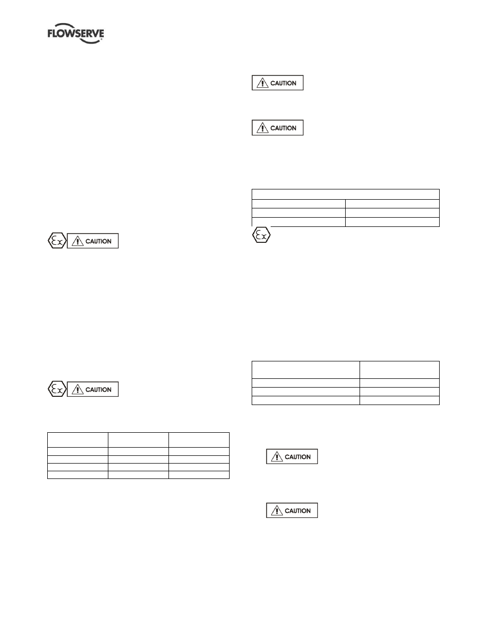
5.8.8
Stop/start frequency
Pump sets are normally suitable for the number of
equally spaced stop/starts per hour shown in the
table below. Check capability of the driver and
control/starting system before commissioning.
Motor rating kW (hp)
Maximum stop/starts
per hour
Up to 15 (20)
15
Between 15 (20) and 90 (120)
10
Above 90 (120)
6
Where duty and standby pumps are installed it is
recommended that they are run alternately every week.
5.9 Stopping and shutdown
a)
Close the outlet valve, but ensure
that the pump runs in this condition for no more
than a few seconds.
b)
Stop the pump.
c)
After stopping a jacketed pump,
leave the steam supply on for approximately 20
minutes. Keep steam circulating in stand-by
pumps.
d)
Switch off flushing and/or cooling/heating liquid
supplies at a time appropriate to the process.