Not supplied – Flowserve HED Worthington User Manual
Page 16
HED/HED-DS USER INSTRUCTIONS ENGLISH 85392695 – 06/14
Page 16 of 64
Figure 4.1
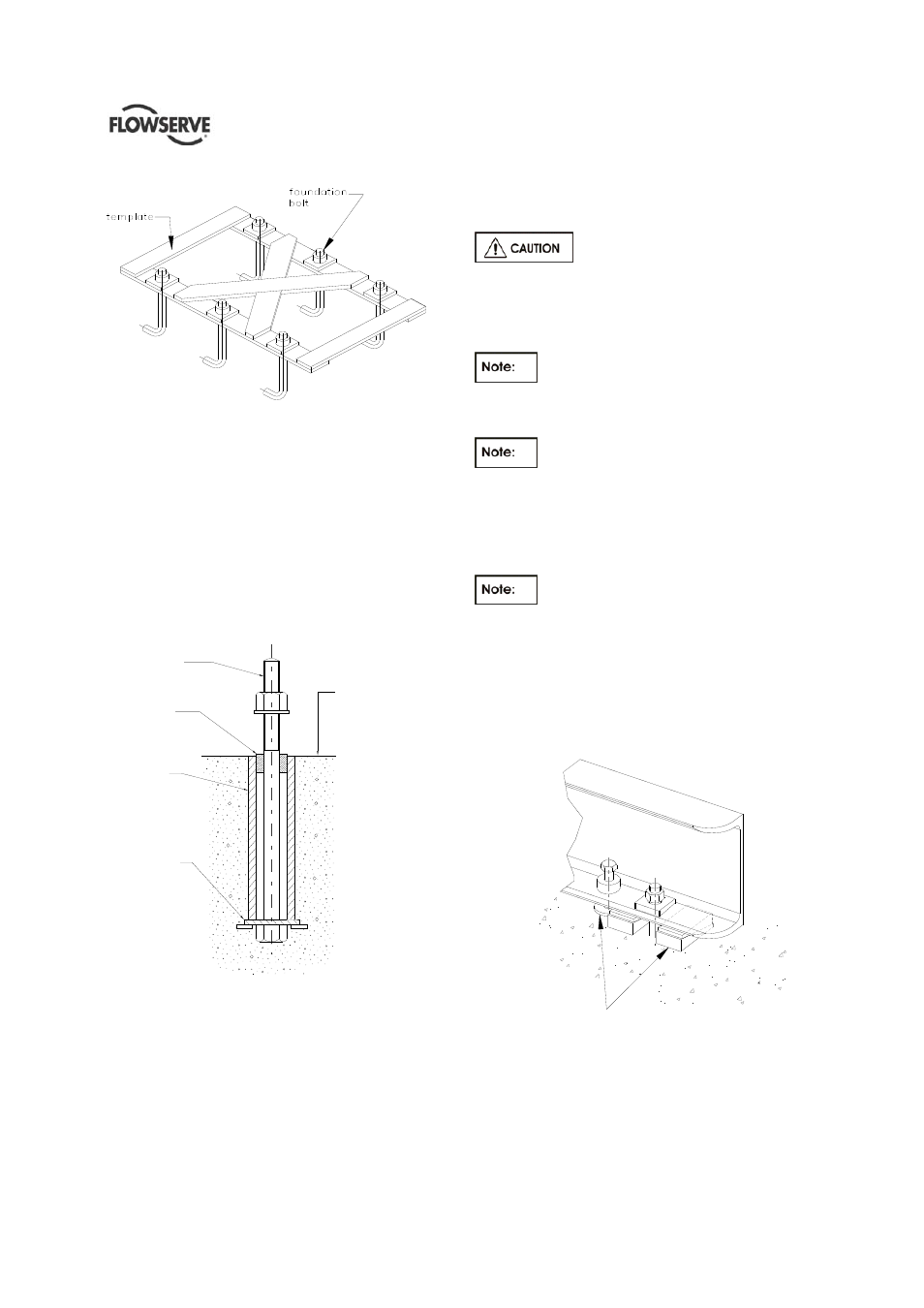
Template for Hanging Foundation Bolts
Figure 4.2 below illustrates an alternative foundation
bolt arrangement which can be used in lieu of
standard foundation bolts. Notice the large washer
with lugs at the bottom. It should be welded to the
bolt and pipe sleeve to prevent turning. Allow a little
more than the specified threaded bolt length above
the rail of the baseplate. The excess can always be
cut off if it is not needed. A rough finish top surface is
best when applying grout.
ALLOW AMPLE THREADED
BOLT LENGTH ABOVE
ROUGH CONCRETE
STUFF WASTE AROUND
BOLT WHILE POURING
CONCRETE
PIPE SLEEVE TO BE
THREE TIMES DIAMETER
OF ANCHOR BOLT
ROUGH FINISH
FOR GROUT
WELD A LARGE WASHER
WITH LUGS TO THE
BOTTOM OF BOLT
AND PIPE SLEEVE TO
PREVENT TURNING
Figure 4.2
4.3.1 Baseplate levelling
Before putting the unit on the foundation, thoroughly
clean the top of the foundation. Break off any loose
pieces of cement and roughen the top with a chisel to
afford a good hold for grout.
In case of installation over a steel structure (platform)
ensure that the top of the steel structure is cleaned
and degreased.
In order to obtain the parallelism and
flatness of pads required by API standard, baseplate
has to be properly levelled by levelling screws
provided on it and clamping the baseplate at the
foundation bolts only (For proper detailed procedure
refer to Chapter 5 para 3.9.4 of API RP 686 ).
Coupling bolting and spacer piece must
be removed from between the pump and driver half
couplings before lifting baseplate with pumping
element.
When the unit is mounted directly on
structural steel framing, it should be located directly
over as near as possible to the main building
members, beams, or walls. A soleplate should be
bolted or welded to the steel frame to guarantee the
proper surface.
When lifting baseplate with pumping
element, sling baseplate from all lifting lugs provided.
Refer to Section 2.3.1
Prepare sufficient steel plates to be placed below
each baseplate jacking screw furnished with the
baseplate. The purpose of the plate is to spread the
load of the screw without crushing the concrete
below.
Not supplied
Figure 4.3
4.3.2 Method of levelling baseplate using wedges
or shims
a) Level the baseplate by using a machinist's level
on the machined surfaces of the pump and driver